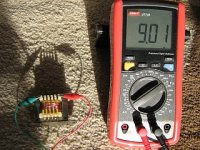
I have a couple of little commercial audio transformers which by manufacturer's spec have a single primary winding with sections of 900 turns, 600, 400, 300 and 725 turns;
so I thought 900+600=1500 turns are almost center tap with the rest 400+300+725=1425 just 75 turns short;
that said, I add the 75 turns of wire, connect it to the shorter half and measure inductance before and after to check symmetry;
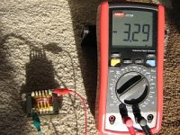
original primary had 9 Henry, the extended primary (surprise !) - 3 H (minus three !)
now that I don't believe ;-)
first I thought this means over range, but range is 20H;
the new turns follow the orientation of the others and there is no shield;
the negative numbers show up every time the new turns are included in the loop;
I modified four of these transformers and they all show this behavior ...
does anybody know, how these "multi-meters" measure inductance ?
so I thought 900+600=1500 turns are almost center tap with the rest 400+300+725=1425 just 75 turns short;
that said, I add the 75 turns of wire, connect it to the shorter half and measure inductance before and after to check symmetry;
original primary had 9 Henry, the extended primary (surprise !) - 3 H (minus three !)
now that I don't believe ;-)
first I thought this means over range, but range is 20H;
the new turns follow the orientation of the others and there is no shield;
the negative numbers show up every time the new turns are included in the loop;
I modified four of these transformers and they all show this behavior ...
does anybody know, how these "multi-meters" measure inductance ?
Attachments
I find it hard to believe it can even display a negative inductance, not such a thing in the multimeter world.
So we have either a malfunctioning meter or an impossible riddle.
So we have either a malfunctioning meter or an impossible riddle.
Probably means the inductor is looking capacitive at the test frequency (i.e., test freq is beyond its resonance) If you have a tone gen and a scope best to set up a filter with the inductor in series with a resistor (of maybe 5000 ohms), meas voltage across the resistor.
Meters get fooled. If I take a resistance reading with some residual voltage in the circuit, it shows a "negative resistance" readings.
bwaslo is right, it's because of parasitic capacitance. The winding capacitance is probably making a resonant circuit at the test frequency so the meter sees an even larger voltage across the DUT than it is supplying, hence the negative value.
so, if it's excessive capacitance, then the question turns into - why should 75 turns on top of 3000 increase capacitance so much that it fools the meter ?
my sloppy winding technique, turns not strictly side-by-side but sometimes on top of each other ... it is repeatable though ...
my sloppy winding technique, turns not strictly side-by-side but sometimes on top of each other ... it is repeatable though ...
My experience is that when something impossible seems to be happening, it usually turns out that what is actually happening is not what seems to be happening or what the builder intended to happen. It turns out that what is actually happening is possible.
Check, double-check, triple-check your windings and connections. Could stray capacitance be amplified by transformer action? What frequency does the meter use?
Check, double-check, triple-check your windings and connections. Could stray capacitance be amplified by transformer action? What frequency does the meter use?
Well, I double checked with a simple method, putting 24v 50Hz ac across the primary and measured voltages for each section and tap and got exactly the numbers expected from turns ratios, so I'm pretty shure that windings / orientation are O.K.
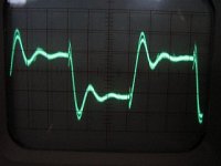
Now I hooked up a scope and as soon as the earth wire from the scope is attached, the negative disappears and numbers match expectations; it seems the meter (at least in 20H range) puts out a 555 Hz square wave - possibly constant current - 40mV amplitude when measuring an 8H coil, which drops to 10mV for a 2H - so it seems to do a simple impedance measurement with a square wave...
(In the lower ranges amplitude and frequencies are different)
With the scope attached the negatives are gone but tinkering with the probe on other taps they reappeared - and it seems that something with the signal generator in the meter goes awry: the frequency jumps to 5.5MHz and amplitude is now 2volts - no wonder the ucontroller in the meter gets it all wrong !
Attachments
- Status
- Not open for further replies.
- Home
- General Interest
- Everything Else
- choke or joke ?