I have build a choke-input (LC)-power supply for a SS-Amp with a 40mh-choke, at 6A. The choke has a resistance of 2,2ohm. The amp is an Aleph-X, so has 6A and runs in class a, so constant current draw is guaranteed. It works very nice, but I want to add a snubber across the choke to minimize stress on the choke like vibration etc.
I read through quiet a bit of documentation like
http://www.hagtech.com/pdf/snubber.pdf
For a tube amp, I have rules of thump like 10k-resistor in series with 1uF across the choke. But there I have 10H and a feww hundres volts and only 100mA!
So how do I calculate it for low voltage with high current correctly ?
Thanks a lot
The optimum snubber value is based on the recovered charge of the diode, and to a lesser extent on the circuit di/dt. The effective recovered charge in switching depends on diode type, operating temperature, forward current, and rate of di/dt in commutating the diode off. The snubber goes across the diode, to control the snappiness of the diode turn-off and damp the ringing in the circuit.
I can't really see any obvious benefit to putting some type of network in parallel with the inductor. Seems to me it would just create a parallel resonant circuit with the inductor, though with enough resistance in the RC snubber the Q would be low. The only reason I can imagine a "snubber" across an inductor would be to reduce the possiblity of voltage transients in some sensitive part of the circuit due to the voltage compliance which a pure inductor has, operating as a current source; a snubber might prevent overvoltage in some other circuit component, but it would also compromise to a degree the current regulation properties.
I've built a couple of AB style high power amps with inductor input power supply; other than the expense of getting good inductors (don't even ask what Plitron charges for 25A 15 mH inductors!), the results are very nice for a solid state amp. Only a few commercial models have done this, such as Ayre, Cello, and Music Fidelity.
One nice think about large inductors/chokes is that they are real sturdy items... I don't think you need to worry about reducing stress on the inductor. 😉 Even if you saturate the inductor with a temporary high volt seconds and go beyond the rated DC value, it will recover nicely without any lasting damage, unless it's been sitting in such a mode for so long that the heat build up is bad enough to damage the insulation. A snubber wouldn't affect this kind of overload.
My background is both SMPS design and audio, so I'm trying to look at this from both angles.
BTW, the easiest way to avoid being much concerned with diode snubbers is to use Schottky diodes, which only have a simple depletion capacitance, and no recovered charge. Then a "optimum" snubber can be calculated which doesn't depend on load conditions or operating point, just on the diode depletion capacitance.
This is why HV Silicon Carbide Schottky diodes (300V, 600V, 1200V) are becoming popular for some high density power supply applications, as they behave much closer to an ideal diode than most other available components.
Regards,
Jon
Jon,
Thanks for your fast response. I have built a couple of amps, but mainly tube amps. I made there already the experience that chokes can start to buzz and that either a small cap before them to earth helps without taking away thesonic advatnages of a choke-input our a snubber can help across the choke. My chokes here in the Aleph-X are of excellent quality and there is minimum buzzing...but being a perfcetionist, I try now to get rid of that as well so that the power supply is true quiet.
My question came arose from the comments Morgan Jones had in his book "VAlve amplifiers":
"We said that the choke input power supply drew a constant current from the mains transformer, but this is not exactly true.Since the rectifier diodes require a certain voltage before they switch on, there must be a time as the input waveform crosses through zero volts, when neither diode is switched on. The current drawn from the transformer is therefore not continous, and must fall momentarily to zero. The choke will try to maintain current and by doing so will develop an e.m.f.:
E=-L*(di/dt)
A resistor/capcitor snubber network should be fitted across the choke to limit these spikes"
I must correct my statement above: He suggests a 10nF and 10K snubber across a 10H choke. HE states that high frequencis filtering will become bad as well through this snubber, so I ask myself if a small capcitor to ground is not the better soultion.
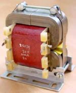
By the way: the chokes come from http://www.ae-europe.nl/smoorspoelen.htm
They get with 6A through them really hot (how hot is still OK?) and funny enough become more silent when they get so hot (after one hour).
Thanks for your fast response. I have built a couple of amps, but mainly tube amps. I made there already the experience that chokes can start to buzz and that either a small cap before them to earth helps without taking away thesonic advatnages of a choke-input our a snubber can help across the choke. My chokes here in the Aleph-X are of excellent quality and there is minimum buzzing...but being a perfcetionist, I try now to get rid of that as well so that the power supply is true quiet.
My question came arose from the comments Morgan Jones had in his book "VAlve amplifiers":
"We said that the choke input power supply drew a constant current from the mains transformer, but this is not exactly true.Since the rectifier diodes require a certain voltage before they switch on, there must be a time as the input waveform crosses through zero volts, when neither diode is switched on. The current drawn from the transformer is therefore not continous, and must fall momentarily to zero. The choke will try to maintain current and by doing so will develop an e.m.f.:
E=-L*(di/dt)
A resistor/capcitor snubber network should be fitted across the choke to limit these spikes"
I must correct my statement above: He suggests a 10nF and 10K snubber across a 10H choke. HE states that high frequencis filtering will become bad as well through this snubber, so I ask myself if a small capcitor to ground is not the better soultion.
By the way: the chokes come from http://www.ae-europe.nl/smoorspoelen.htm
They get with 6A through them really hot (how hot is still OK?) and funny enough become more silent when they get so hot (after one hour).
Attachments
"how hot is still OK?"
Depends on the core material properties versus temperature. Temperature characteristics of insulation on magnet wire. What other components could be affected by this heat. Temperature caused expansion and contraction stress.
In general, I like to keep the temperature rise to no greater than 30 degrees C above ambient. Many times this is neither practical nor necessary though, and a higher temperature rise should be considered. Obviously, reliability should be considered depending on many factors.
Measure inductor/core temperature rise and inside enclosed unit air temperature with worst case room ambient temperature, since you are a perfectionist. Not a bad idea for the non-perfectionist. Try to get the thermocouple (temp. probe) on the core with thermally conductive grease, near the center of the core or towards the center of the inductor unit. If you are building your own inductors, you can embed a thermocouple in the copper windings, also. Wait for temperature to stabilize.
Being a perfectionist can be an asset sometimes and a curse at other times, IMO.
Ok, you punished me for the perfectionist stuff enough.😉
So, I measured 60 degree celsius at the chokes (which are of the type I posted). Good enough ?
Any thoughts on the snubber ?
So, I measured 60 degree celsius at the chokes (which are of the type I posted). Good enough ?
Any thoughts on the snubber ?
Blitz said:Ok, you punished me for the perfectionist stuff enough.😉
So, I measured 60 degree celsius at the chokes (which are of the type I posted). Good enough ?
Any thoughts on the snubber ?
Unfortunately I'm a perfectionist, also. It did come in handy for doing worst case analysis on others' designs. Painful for them, though. Sorry, my intention was not to punish. Just joking.
If your ambient is 25 to 30 degrees C, considering the core material in the picture, that should be good enough. Is that in an enclosed unit with vented slots, etc.? Most metal laminate cores can really take the heat, in my experience.
I need more study on the snubber. I have not looked at a circuit diagram on exactly what you are doing, but I plan to after taking my dog for a hike or vice versa.
To give you a better picture: I used these Diodes: http://www.schuro.de/Daten/IR/hfa25pb60.pdf
Voltage is 30 VAC at the transformer, 23VDC after the choke-input filter.
Voltage is 30 VAC at the transformer, 23VDC after the choke-input filter.
Seem like nice rectifiers (diodes). I'm still playing catch-up.
I'm assuming you used full wave rectification off the transformer secondary and go into the choke with a large filter cap to ground. Your choke winding resistance is 2.2 ohms and your load of 6 amps at 23VDC means a load of 3.83 ohms. I'm assuming you use a single supply voltage for your amp (Class A).
Center tapped transformer secondary and 2 diodes or no center tap and full bridge?
40mh at 100 Hz fundamental. XL = 2*pi*f*L = 25 ohms impedance approximate due to rectified AC. How much capacitance for the C part of the LC filter?
Do you see high frequency ringing anywhere? If not forget the snubber. If so, what's the frequency of this ringing?
A large choke with a lot of turns is really only good for filtering low frequencies. It will have a relatively large shunt winding capacitance that passes high frequencies like a short circuit, almost. If you have high frequency noise with these rectifiers (diodes), then you will need another method of blocking it. A small choke with a small number of turns in series with this large choke maybe. Some suggest putting small valued resistors in series with rectifiers and/or small valued capacitors in parallel. There are others on this forum with more power supply experience and more recent experience with newer rectifier technology than me. I want to learn more about reducing noise and ringing, also. Those high voltage Schottky diodes sound interesting!
I'm thinking about how much energy the capacitor in the snubber will need to absorb in order to size the capacitor. Once the capacitor value is known, calculating the resistor value is easy.
I realize it's bedtime in Germany.
Do you use a small value capacitor (1uf or similar) at the input of the choke? I don't yet see the need for a snubber for the choke, unless it rings at it's own low self-resonant frequency. Not seen that happen. I think rectifier ringing, if present, will be very high frequency based on lead inductance, junction capacitance, and transformer parasitics. I agree with Jon, can't see a need for a snubber for the choke, but there's a good chance you can have rectifier ringing.
Do you use a small value capacitor (1uf or similar) at the input of the choke? I don't yet see the need for a snubber for the choke, unless it rings at it's own low self-resonant frequency. Not seen that happen. I think rectifier ringing, if present, will be very high frequency based on lead inductance, junction capacitance, and transformer parasitics. I agree with Jon, can't see a need for a snubber for the choke, but there's a good chance you can have rectifier ringing.
mwh-eng said:I'm assuming you used full wave rectification off the transformer secondary and go into the choke with a large filter cap to ground. Your choke winding resistance is 2.2 ohms and your load of 6 amps at 23VDC means a load of 3.83 ohms. I'm assuming you use a single supply voltage for your amp (Class A).
Center tapped transformer secondary and 2 diodes or no center tap and full bridge?
40mh at 100 Hz fundamental. XL = 2*pi*f*L = 25 ohms impedance approximate due to rectified AC. How much capacitance for the C part of the LC filter?
Do you see high frequency ringing anywhere? If not forget the snubber. If so, what's the frequency of this ringing?
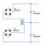
Yes, full-wave with two secondaries and two bridges, balanced powersupply with +23V and -23 V, therefore two chokes and a capacitance of 100000uF behind the choke.
I have started to debug the power supply for high-frquency ringin with the osci, I first wanted to get rid of the buzzing (sound like high-frequency though) of the chokes.
A small cap (100-470uF) before the choke brings the buzzing you can hear from the chokes down from high-frequent to the more normal 100Hz
On the high-frequency filtering: As we have 6A current drawn , I would loose 3V when attaching a 0,5R into the rail...so the resistor should be smaller like 0,25R. How much additional filtering will this give compared to the DC-resistance of the choke which is already 2,2 Ohm ? And where to place it: Making it RLC, RCLC or LCRC ?
Best Regards
Blitz said:
Yes, full-wave with two secondaries and two bridges, balanced powersupply with +23V and -23 V, therefore two chokes and a capacitance of 100000uF behind the choke.
I have started to debug the power supply for high-frquency ringin with the osci, I first wanted to get rid of the buzzing (sound like high-frequency though) of the chokes.
This is per channel.
Correction: I have not started to debug for high-frequency ringing, how do you see it on the osci by the way ?
Hmmmm, 2. 2 ohms with a DC current of 6A is a little higher resistance than I'd prefer. Power dissipation is I^2 X R, which is around 72 watts average in your case- this is why you have a 60 degree rise over ambient. But magnet wire is rated to ~200-250 C, in most cases, so you should be fine, apart from the power loss.
Another thought to ponder, and somthing you can measure- the copper winding has a temperature coefficient, and as the inductor heats up, the resistance increases. There may be some combined affects when you amp has been on and running for some time, that is reducing slightly the overall current through the choke, maybe less than 10%. But this could be taking you a little further away from the saturation point of the core, and quieting it down. Is your core rated at 6A max? The thing is, one usually wouldn't use the core at the full rated DC, because there is an AC ripple current which rides on top of the DC value (which is a function of the lines frequency and inductance); the actual working current will be then higher than the 6A rating. Is this happening in your case? You may be better off with an 8A rated inductor, for example, carrying 6A average DC current. The only drawback, of course, is that it's more expensive. But, you were saying something about being a perfectionist? 😉
As long as you're doing a true choke input supply, ie. rectifiers to the choke, and it smoothing the current draw into the first primary filter bank by operating in continuous conduction mode, (which greatly lowers the peak rectifier on the AC mains and almost doubles the transformer utilization factor), you can have some potential for mechanical hum in the transformer, because the current isn't flat, at best, but has a sinisoidal ripple current which is a function of the AC frequency and the inductance.
What it sounds like you're looking at on the input side to the inductor to prevent interruption of the current path when the diodes are all in blocking is like the bypass capacitor used in a primary side active PFC circuit; this is usually one to two microfarads film capacitor connected across the output of the diodes. In this case the "switching" frequency is much lower, and the current higher- you might want to take that up to 10 uF or so. This should be a low ESR, high quality film cap. If the supply is singled ended, then wiring it to the diode outputs and to ground should do the trick.
If you could post a schematic of your basic supply configuration, it would be easier to comment.
Glad Jon thought about the I^2*R loss. 79.2 watts dissipation is too high. Make sure you really have 2.2 ohms winding resistance and your amp is pulling 6 amps DC current. For both + and - supply this is 158.4 watts dissipation. Ouch! I would think the chokes would smoke. I'm sure they will cause a blister if you get too close. I think you need chokes with much less winding resistance for your application.
If your scope is not isolated and is a three wire, with earth ground connection to AC power, then connecting your scope ground probe to the secondary ground will tie your secondary(s) to earth ground. Should not be a problem. Look at the signal on each side of each rectifier. Better to use differential probe setup to measure directly across rectifiers. Don't connect the scope ground probe to any rectifier lead unless your scope is fully isolated. You should apply normal range of loading for measurements. Be careful with these measurements. Wait for someone else here, to post to either confirm or not confirm my measurement suggestions, unless you have such experience.
Would be good if you could post a schematic as Jon suggested. Do you have Spice, LTspice, etc.? Good way to quickly check for continuous current in the inductors. Only need to model one supply. You can calculate if you have continuous current. It's been 15 years for me, so I'm still scratching my head and rather use Pspice.
If you heard a high frequency noise from the choke, then you did have high frequency ringing. Need to find the source of this ringing. Your transformer leakage inductance and the rectifier junction capacitance is suspect.
Good luck and keep us posted.
mwh-eng said:You can calculate if you have continuous current. It's been 15 years for me, so I'm still scratching my head and rather use Pspice.
A nice overview and calculation directions for the critical inductance for continuous current is given on: http://www.qsl.net/i0jx/supply.html
Steven
Steven, very cool link, thanks a lot. When I calculated right, I can get away with a ten times smaller choke in inductance using a RESONANT CHOKE POWER SUPPLY. Wow !
I will make now some experiments. 72 Watts is a lot...fortunately the chokes are center-tapped, so I can use as well only half of the winding, bringing DC-resistance and inductance down. Let's see how this is. And I will test definitely the RESONANT CHOKE POWER SUPPLY...I could do this even with some coils I have from building some cross-overs ! Very cool.
I will make now some experiments. 72 Watts is a lot...fortunately the chokes are center-tapped, so I can use as well only half of the winding, bringing DC-resistance and inductance down. Let's see how this is. And I will test definitely the RESONANT CHOKE POWER SUPPLY...I could do this even with some coils I have from building some cross-overs ! Very cool.
Blitz said:...fortunately the chokes are center-tapped, so I can use as well only half of the winding, bringing DC-resistance and inductance down.
Maybe you can separate the two windings that use the common center tap. Then use one for the positive supply and one for the negative supply. Make sure that the current direction is the same in both, so the magnetic fields should NOT cancel. In this way you double the inductance of each coil, just because there is current in the other one and they are magnetically coupled.
Actually, now I think about it, maybe you don't have to separate the windings. Use one in the negative rail of the positive supply and one in the positive rail of the negative supply. The center tap is the new ground where the supply capacitors are connected to.
Steven
Attachments
I just forgot:
- Use a resistor in parallel with each choke as damper, guideline 10..100 Ohm. This allows for smaller snubber capacitors across the bridges.
- Connect a big 4.7u foil capacitor across each bridge, from plus to minus (more effective than across AC terminals). Normally such a capacitor needs a series R to dampen the LCR with the secondary of the transformer, but the optimum value of the resistor in series with the C is approx sqrt(L/C) with L is the secondary inductance and C the value of the C. The 4.7uF seems big enough to allow for a value of R that is close to the series resistance of the secondary, so effectively the LCR is dampened already.
Steven, thanks again, these are very helpful hints. So, I experimented a bit:
- When I use two chokes with 40mH and 2,2 ohms with the two bridges, one in the + and one on the minus rail, I have a DC after the capacitor bank of 100000uF of approx. 22,5V. My ripple is down to 25mV. The choke is buzzing a little bit with 6A (being specified for 6A).
- When I use both choke in the same configuration, but taking the voltage out already at the center-tap instead of the whole winding, the voltage increases by 1,5V and ripple is now 33mV. The chokes are buzzing louder than before.
- When use the last configuration you showed in the picture, Steven: I have now 23,4V, so one volt more than originally, a ripple of 55mV and the choke is absolutely dead-quiet. It may be the case that the transformer is now buzzing a bit, but that may be an illusion as well.
Do you have any explanation ofr these observations ? I would prefe to go with the last option, but is this than longer a choke input-PSU ? How nuch bigger are the current-spikes asked from the transformer now in comparison to the original setting ? Is there any RF-filtering as there are now no series-elements in the + and - rails ?
OK, just two additional observations:
- after an hours of operations, the choke is now buzzing as well, ripple has come down from 55mV to 48mV
- Even though I have a soft-start-circuit in place (0,5sec over a 27 resistor, than shorted by a relay), each time I switch it on directly without a variac, the automatic fuse of my house reacts and I am sitting in the dark. How do this come ?
Nevertheless I feel that this setting has its advanta´ges as I need only half of the number of chokes, which is max. half of the heat and I save two chokes for another projects...if there are no downsides like strong current-peaks etc ?
- Status
- Not open for further replies.
- Home
- Amplifiers
- Solid State
- Choke-Input: How do I calculate the right snubber for high-current-low-voltage