hi guys,
I was wondering the ecaps at c1,c2,cm have any impact on the sonic qualities of the amp.
Would it matter if the C1 and C2 are of different value, I busted 1 C2 on the amp board, and i couldnt get a replacement of the same brand and value, I only have some 220uf with me.
I am wondering if it will affect any thing if I am going to use some 220uf/50v on the c2 spot on both amplification board.
ratza said:Why don't you just place them on the board and see yourself how it sounds?
Would it cause any imbalances?
hi andrew, nice to see you.
I have gotten the boards from chipamp.com
and the manual from here, http://chipamp.com/lm3886.shtml
I just soldered in a 220uf in the c2 and the whole amp is working, on a chopping board though. Sounds okay, but am not sure cos its a little weird as of now and I am thinking it might need some run in.
Do you see any potential problem for this c2 to be of a different from the 100uf stipulated in the manual?
The next concern i have is regarding the heat. It was on for a moment and ts running hot. I am planning not to use any heatsink but mount the chip on the bottom panel of the chassis, which is rather large, at about 45cm x 30cm, would that be sufficient.
That cap value is okay; however, if its a main rails cap, it needs to be the same value as its partner.
The weird sound you're experiencing is probably coming from clipping and / or the metal 1k resistor.
See my post here on how to "unscreech" the kit.
http://www.diyaudio.com/forums/showthread.php?postid=1403686#post1403686
Thermal paste like Artic Ceramique, should be used. For direct to chassis mount, you need a heat spreader. That's a 3cm square thick metal plate with thermal paste on both sides. The chip bolts to that thing and that spreads the heat *away* from the chip and onto the larger metal surface beneath it.
A chassis also needs an air intake below the chip and an air outlet above the chip for venturi/convection ventilation--otherwise you have created an oven. 😉
EDIT: In this case, the small, thick, heat spreader bolts to the case with four screws. The chip bolts to the heat spreader plate.
Have fun with the little kits. They *can* be good.
Assuming that i dont do the unscreehing of the treble, would it be alright for me to just mount the chip directly on the base panel.
probably not.marcusdeming said:........would it be alright for me to just mount the chip directly on the base panel.
marcusdeming said:Assuming that i dont do the unscreehing of the treble, would it be alright for me to just mount the chip directly on the base panel.
This depends on:
Voltage?
Thickness of the base panel?
Can cool air get into the enclosure?
Can warm air get out of the enclosure?
You can locate a huge metal washer on bottom of the enclosure--use thermal paste! This washer can be heat spreader.
The bolt that goes through the washer can hold the chip to the inside of the enclosure--use thermal paste!
You can drill holes into the bottom of the enclosure, about 1 to 3cm away from the washer, so that air can transport the heat.
You can provide a warm air outlet with some holes or vent at the top of the enclosure.
I do have some vents at the top and side of the chassis, I would post some pictures when i get home.
The c2 caps are actually the one that is on the 2 side of the amp board, I think a picture would be best, I would post some of them when i get home.
The c2 caps are actually the one that is on the 2 side of the amp board, I think a picture would be best, I would post some of them when i get home.
I found your replacement cap.
Your replacement capacitor is located at CM--code of CM means Capacitor for Mute switch (CM).
If this is an exact match for the broken cap, then use it.
That position works the mute switch, which is either on or off, so your un-matched replacment cap can go to CM.
A case needs both an air inlet and an air outlet. The air inlet will be as close as possible to the warmest spot. The air outlet will be at or near the top of the case.
Oh yes, thanks, why didnt i think of that. I guess i know why it sounded weird the last time, maybe its because c1 and c2 are of different caps.
Yes my Cm is the same cap used. I am using nichicon now, the gold coloured one(not fine gold), and I was wondering if there are better caps that i should considered for c1 and c2, since i am going to do some re-soldering one way or another.
Rgds.
Yes my Cm is the same cap used. I am using nichicon now, the gold coloured one(not fine gold), and I was wondering if there are better caps that i should considered for c1 and c2, since i am going to do some re-soldering one way or another.
Rgds.
Nichion is already a better quality cap. This is suitable for power needs.
For the audio circuit cap, you may wish to acquire a BlackGate model that is reviewed as "warm sounding" because that is beneficial.
That would be the 22uf or 33uf or 47uf in the audio signal circuit--that is listed as "optional" in most chipamp kit instructions.
It isn't really optional--it protects your speakers by preventing DC output.
Since this behavior varies between individual chip samples (manufacturing variance), then preventing the behavior is the way to get stereo (both chips match performance) that matches per left and right.
Other weird sounds:
There are four resistors in the usual kit's audio signal.
These are usually blue.
If they're tan/beige color, count yourself lucky and skip to the next paragraph.
Two of them will have values between 680 ohms, 1k, or 2k.
Its time to play "spot the plonker." You can remove some weird sounds by changing those two (or all of them) to the tan colored resistors.
Tan resistors with a Gold stripe is 5% carbon (good), and carbon has a "smoothing" effect on non-audio noises.
That's helpful to LM3886 so that it doesn't amplify the hetrodyne on digital sources (possible source of the weird sound you describe).
The fifth resistor that you'll see on most kits is the mute switch resistor.
*Check these components with a multimeter to insure that you have exactly the same values per left and right for stereo.
Steel wool and flux:
You can swipe the soldering iron across a bit of steel wool so that the tip is brilliantly shiny--each time before soldering an audio connection.
A tiny bit of flux is very helpful to insure a good, solid connection at a solder joint. This insures that there won't be any mysterious static.
Application of flux, and a tiny bit more solder, onto existing solder joints, can correct them.
Optional components:
Some of the kits don't contain speaker output zobels. That's not okay. Absence of the zobel would make the amp quirky about speaker cable choices.
Alternatively, you can use 0.1uf miniature polyester (cheap sort) directly across the speaker terminals. That does a similar job. It can work in addition to an onboard zobel.
This optional output filter components prevent weird behaviors by decreasing transmission/amplification of non-audio signals, such as ultrasonic hetrodyne cascades. And, preventing the problem makes lower listening fatigue.
My own LM3886 kit amplifiers had six choices that were all capable of amplifying non audio signals. All of them did exactly that. Not only was the amp exhausted so that it wasn't powerful to amplify audio but it also sounded weird.
This had been advertised as "extra detail." But, none of it was an audio signal--it was noise, mostly in ultrasonics that hetrodyned to divide and then cascade (by octaves) down into the audio bandwidth. I am unsure whether the components themselves created the noise or whether the extra non-audio labor had partially set off the Spike protection.
Most females and most younger men would hear a painful "screeching treble" coloration; however, most adult men would not perceive this.
Purposeful clipping:
Another cause of a weird sound is the Spike power-limiter's purposeful clipping. It is especially aggressive in LM3886.
The LM3875T and LM1875 are less likely to engage Spike.
It doesn't switch on/off, but rather it is a variable effect that engages slowly at first with a hint of raspy sound.
Inappropriate thermal management is the most widely documented way to set off Spike. Do plan your thermal management carefully.
Amplifying non-audio signals is the most common way to set off Spike; however, that one is a bit mysterious because most adult males cannot hear it partially engaged. 😉
Not only does the noise cause harm to women, children, and pets, but it also gives the amplifier an unnecessary workout and sets off Spike--long before advertised power output is reached.
More useful power=more power:
My mod, in the link above, is a brute force way to restrict the amplifier to audio signals. That increases its useful power output.
The filter capacitor listed (in the link, post 1403686) is for full range (floorstander) speakers. However, bookshelf speakers could use a smaller value like 3.3uf (30hz speakers) or 2.2uf (40hz speakers) or 1uf (65hz speakers). Of course, its not necessary to have the amplifier labor so greatly to produce bass notes that won't come out of the speakers.
Just like cutting the treble bandwidth (down to the audio spectrum) makes less amplifier efforts and increases the useful power. . . so, at your option, you can cut the bass bandwidth to correspond to your speakers, which also makes less amplifier work and increases the useful power.
Increasing the useful power by restricting the amplifier to audio signals--avoids setting off the weird noises of Spike protection.
Whatever name you choose to give to the sound of Spike protection, well, that's up to you. I chose to call it a screech.
Does this explain my reference to Spike's audiable effects?
Does this explain why you would want good thermal management?
Thermals:
At the minimum, that's a heat spreader, a cool air intake, and a hot air output--like any other hard working computer chip.
If you'd like to get one hot without paying dearly through loss of quality, then try LM1875 (very hot) or LM3875 (similar, but cooler). In particular, LM3875TF (isolated) can probably work with a "just bolt it somewhere to the case" approach. Although, I'd still like to see a large metal washer + thermal paste on the outside (probably bottom) of the aluminum case, and with air intake holes around it.
This creates a situation whereby hot air is underneath cool air--it won't stay that way. It quickly moves so that the hot air goes up, thus creating a nonstop breeze. 😉
The common 2x3 inch $1 TO220 /w 90deg fins heatsink is prethreaded for screw mounting onto a PCB board.
This heatsink is small, but, if it is screwed to the bottom of an aluminum enclosure, with air holes underneath it, (and/or the top with air holes above it) then it can be mighty--because the case makes it bigger.
I use those to cool my Thompson's (for music), and high-power-hacked LM1875's which are both quite the challenge indeed. Of course, I put thermal paste between any metal parts that serve heatsink.
Passive Heatsink:
A smaller bit of thick and thermally conductive material that is thermally connected to progressively larger and thinner (or less conductive) materials until, at last, air is able to conduct the heat away. For computers, its a small copper plate that's bolted or glued to a large aluminum fin. For laptops, this large aluminum fin is thermally connected to and bolted to the bottom of the enclosure, which also has a vent at this point. Sound familiar? 😉
That's all I've got for now except. . . do see the link (above post) for more clues on how to prevent amplification of non-audio signals--which is an additional way to keep the chip cool and boost its useful output.
Cheerio!
For the audio circuit cap, you may wish to acquire a BlackGate model that is reviewed as "warm sounding" because that is beneficial.
That would be the 22uf or 33uf or 47uf in the audio signal circuit--that is listed as "optional" in most chipamp kit instructions.
It isn't really optional--it protects your speakers by preventing DC output.
Since this behavior varies between individual chip samples (manufacturing variance), then preventing the behavior is the way to get stereo (both chips match performance) that matches per left and right.
Other weird sounds:
There are four resistors in the usual kit's audio signal.
These are usually blue.
If they're tan/beige color, count yourself lucky and skip to the next paragraph.
Two of them will have values between 680 ohms, 1k, or 2k.
Its time to play "spot the plonker." You can remove some weird sounds by changing those two (or all of them) to the tan colored resistors.
Tan resistors with a Gold stripe is 5% carbon (good), and carbon has a "smoothing" effect on non-audio noises.
That's helpful to LM3886 so that it doesn't amplify the hetrodyne on digital sources (possible source of the weird sound you describe).
The fifth resistor that you'll see on most kits is the mute switch resistor.
*Check these components with a multimeter to insure that you have exactly the same values per left and right for stereo.
Steel wool and flux:
You can swipe the soldering iron across a bit of steel wool so that the tip is brilliantly shiny--each time before soldering an audio connection.
A tiny bit of flux is very helpful to insure a good, solid connection at a solder joint. This insures that there won't be any mysterious static.
Application of flux, and a tiny bit more solder, onto existing solder joints, can correct them.
Optional components:
Some of the kits don't contain speaker output zobels. That's not okay. Absence of the zobel would make the amp quirky about speaker cable choices.
Alternatively, you can use 0.1uf miniature polyester (cheap sort) directly across the speaker terminals. That does a similar job. It can work in addition to an onboard zobel.
This optional output filter components prevent weird behaviors by decreasing transmission/amplification of non-audio signals, such as ultrasonic hetrodyne cascades. And, preventing the problem makes lower listening fatigue.
My own LM3886 kit amplifiers had six choices that were all capable of amplifying non audio signals. All of them did exactly that. Not only was the amp exhausted so that it wasn't powerful to amplify audio
but it also sounded weird. This had been advertised as "extra detail." But, none of it was an audio signal--it was noise, mostly in ultrasonics that hetrodyned to divide and then cascade (by octaves) down into the audio bandwidth. I am unsure whether the components themselves created the noise or whether the extra non-audio labor had partially set off the Spike protection.
Most females and most younger men would hear a painful "screeching treble" coloration; however, most adult men would not perceive this.
Purposeful clipping:
Another cause of a weird sound is the Spike power-limiter's purposeful clipping. It is especially aggressive in LM3886.
The LM3875T and LM1875 are less likely to engage Spike.
It doesn't switch on/off, but rather it is a variable effect that engages slowly at first with a hint of raspy sound.
Inappropriate thermal management is the most widely documented way to set off Spike. Do plan your thermal management carefully.
Amplifying non-audio signals
is the most common way to set off Spike; however, that one is a bit mysterious because most adult males cannot hear it partially engaged. 😉 Not only does the noise cause harm to women, children, and pets, but it also gives the amplifier an unnecessary workout and sets off Spike--long before advertised power output is reached.
More useful power=more power:
My mod, in the link above, is a brute force way to restrict the amplifier to audio signals. That increases its useful power output.
The filter capacitor listed (in the link, post 1403686) is for full range (floorstander) speakers. However, bookshelf speakers could use a smaller value like 3.3uf (30hz speakers) or 2.2uf (40hz speakers) or 1uf (65hz speakers). Of course, its not necessary to have the amplifier labor so greatly to produce bass notes that won't come out of the speakers.
Just like cutting the treble bandwidth (down to the audio spectrum) makes less amplifier efforts and increases the useful power. . . so, at your option, you can cut the bass bandwidth to correspond to your speakers, which also makes less amplifier work and increases the useful power.
Increasing the useful power by restricting the amplifier to audio signals--avoids setting off the weird noises of Spike protection.
Whatever name you choose to give to the sound of Spike protection, well, that's up to you. I chose to call it a screech.
Does this explain my reference to Spike's audiable effects?
Does this explain why you would want good thermal management?
Thermals:
At the minimum, that's a heat spreader, a cool air intake, and a hot air output--like any other hard working computer chip.
If you'd like to get one hot without paying dearly through loss of quality, then try LM1875 (very hot) or LM3875 (similar, but cooler). In particular, LM3875TF (isolated) can probably work with a "just bolt it somewhere to the case" approach. Although, I'd still like to see a large metal washer + thermal paste on the outside (probably bottom) of the aluminum case, and with air intake holes around it.
This creates a situation whereby hot air is underneath cool air--it won't stay that way. It quickly moves so that the hot air goes up, thus creating a nonstop breeze. 😉
The common 2x3 inch $1 TO220 /w 90deg fins heatsink is prethreaded for screw mounting onto a PCB board.
This heatsink is small, but, if it is screwed to the bottom of an aluminum enclosure, with air holes underneath it, (and/or the top with air holes above it) then it can be mighty--because the case makes it bigger.
I use those to cool my Thompson's (for music), and high-power-hacked LM1875's which are both quite the challenge indeed. Of course, I put thermal paste between any metal parts that serve heatsink.
Passive Heatsink:
A smaller bit of thick and thermally conductive material that is thermally connected to progressively larger and thinner (or less conductive) materials until, at last, air is able to conduct the heat away. For computers, its a small copper plate that's bolted or glued to a large aluminum fin. For laptops, this large aluminum fin is thermally connected to and bolted to the bottom of the enclosure, which also has a vent at this point. Sound familiar? 😉
That's all I've got for now except. . . do see the link (above post) for more clues on how to prevent amplification of non-audio signals--which is an additional way to keep the chip cool and boost its useful output.
Cheerio!
hi daniel thats quite a bit of information for someone untrained like me but thanks i will try to understand them one by one.
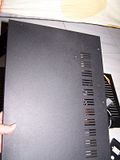
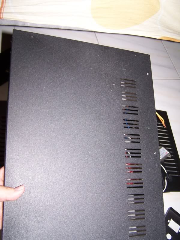
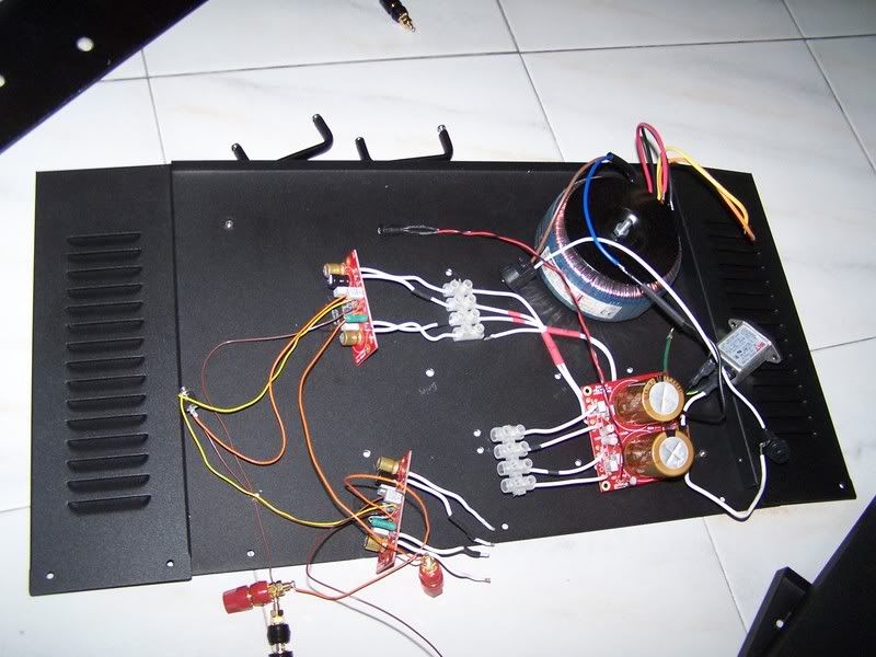
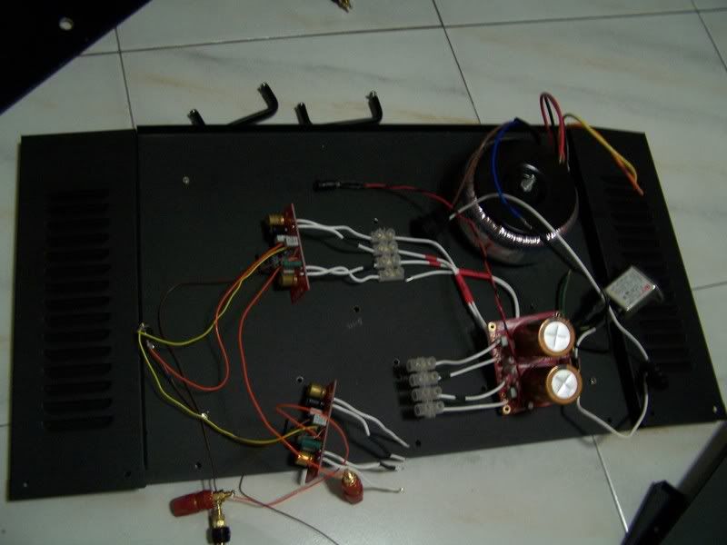
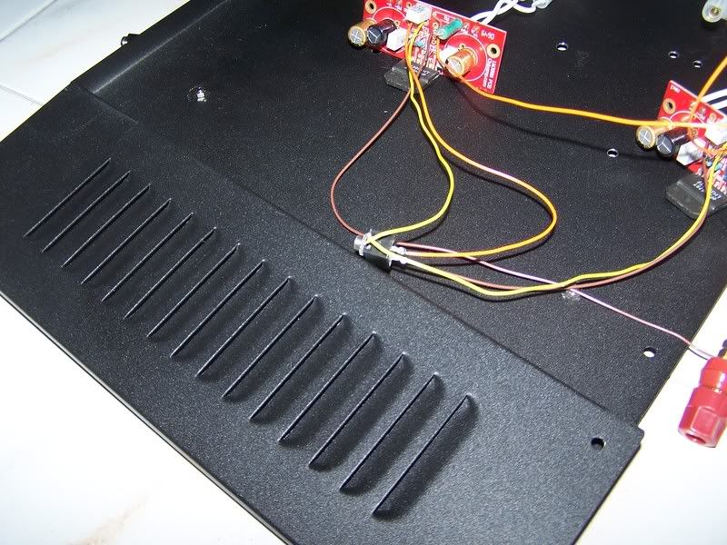
Here are some pictures of my case and would like to check if its alright for me to mount them on the bottom of the case.
The top panel
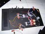
The layout, the chips to be mounted on the bottom panel.
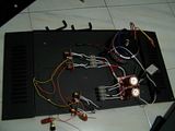
Another look at it
The side panels of the case

There is alot of vents and a couple of extra holes at the bottom panel, so would it be alright for me to mount the chip on the bottom panel. I was thinking of just screwing it down, is it okay?
Here are some pictures of my case and would like to check if its alright for me to mount them on the bottom of the case.
The top panel
The layout, the chips to be mounted on the bottom panel.
Another look at it
The side panels of the case
There is alot of vents and a couple of extra holes at the bottom panel, so would it be alright for me to mount the chip on the bottom panel. I was thinking of just screwing it down, is it okay?
Please use a heatsink.
The bottom of the case is not okay, but there's an easy fix up.
Much of the advise above is relative to options for personal tuning of the amplifier. That's unnecessary if it has a positive reaction to your speakers. 😉
The heatsink information applies to any hard working chip.
First, the chip will contact a bare metal surface. If its painted, use black sandpaper to make it flat, level, smooth and bare.
Second, It will work with the aid of thermal compound to conduct heat out of the chip. My preference is a nice white glob of Artic Ceramique. That's available at any computer shop.
This metal surface will be thick or it won't work. There is a way.
For a thin metal surface (your enclosure), you can attach a very large washer on the opposite side of the thin surface. The term is "heat spreader."
This washer will also contact bare metal, and it will also use thermal compound. The screw that holds the chip will also hold this washer.
Do conduct heat out of and away from your chip. 😉
1) Heat goes out of the chip via thermal compound.
2) Heat goes away from the chip via thick metal heatsink or thin metal that's fitted with a thick heat spreader.
3) Air moves only with both intakes and outputs to help it "flow"
Third, Air is necessary to finish the job of moving heat away from the chip.
At minimum, this could be done by drilling about five 1/4" or larger size holes in the thin metal surface (enclosure), roughly two inches (some variety is good) away from the chip's heat spreader washer or underneath its heatsink. That way, when the metal heats up, air will get pumped through it via natural convection.
Reference: Without an air intake, there is no output.
It does not matter how generous the air output vents are. What matters is that there are corresponding intakes and outputs--else the air won't move. 😉
Voltage: Your thermal needs increase with voltage.
If your DC rails measure 30+30 volts DC or greater, you will want to consider purchasing heatsinks as well as providing sufficient air intake under these heatsinks.
Old pentium 2 "slot" heatsinks may be sufficient and possibly free at the nearest computer store. Otherwise, you can just recycle some nice large heatsinks out of any disfunctional old garage sale/thrift store/curb find sourced amplifier.
For less than 29+29 DC, the "bottom of the case" plus thermal compound and heat spreader washer can work.
Otherwise, I'd have to answer. . . "no" to your question because. . . While the high-heat condition that you're proposing won't actually damage the chip, it will cut the lifespan of the capacitors down to a maximum of 3 years. If they lived that long, it would be sheer luck. But, the failure could come at any time and also wipe out the speakers.
I'm sure that you can find a used heatsink (described above) and employ it to protect your investment. 😉
P.S.
The amplifiers pictured have mismatched caps. Its okay to have a mismatched cap at the "corner" to operate the mute, but its not okay for the power caps to be mismatched. You might want to swap that before connecting speakers. 😉
Pictured is a stereo pair. In that case, its good to make the power wires exactly the same length and type for both amplifiers.
Also pictured is that the DC protection cap is not installed. That might be okay. To find out, measure DC at the speaker terminals before connecting speakers.
Its a nice looking project so far. Please go find a heatsink. 😉
Hi Daniel,
thanks for the reply i have got heatsink actually, just that they are a little too big for my liking, perhaps i will look for new ones.
Is there a size which is good as heatsink.
thanks for the reply i have got heatsink actually, just that they are a little too big for my liking, perhaps i will look for new ones.
Is there a size which is good as heatsink.
Sure. How much voltage is going into the amplifiers?
You can answer either giving your transformer AC voltage (the sticker on its side) or actual DC output of the supply. Either way, I can give you an estimated heatsink size by looking up the requirements on National Semiconductors LM3886.PDF or by using their handy application spreadsheet.
However, if this heatsink is screwed directly to the metal case (now its a heat spreader), with plentiful air intake holes underneath it, then the heatsink size requirement is much smaller because the case/enclosure can help it out. 😉
First, what's the voltage?
- Status
- Not open for further replies.
- Home
- Amplifiers
- Chip Amps
- Chipamp lm3886 qns