Hey guys,
I'm a total newbie to the audiophile world. I just got a Bose Lifestyle 25 Series II 5.1 surround sound system. The room I set it up in does not have any carpet or anything to cover up the wires running to the rear satellites, so I want to make them wireless. This is my setup to do so:
Bass module->Composite transmitter->Composite receiver->Amp->Satellites
The transmitter and receiver I'm using is the Terk Leapfrog. Because the satellites are passive and the receiver sends out a line-level signal (I believe, and if my terminology is correct), the satellites aren't producing any sound. My solution is just to stick an amp of some sort between the receiver and satellite, along with a fuse to prevent blowing out the satellites.
My main question is what sort of amp do I need? I was looking at class-d and class-t chip amps, but the TDA2030A caught my eye. I know that one is class-AB. Also, Bose doesn't divulge much information on their products, but this is what I have been able to gather so far on the satellites using my multimeter:
Resistance: ~6-7 ohms
Voltage from bass module @ C8 (4186.01hz): 1.118v
RMS ( voltage*voltage / resistance ): .18w-.21w
There is also this specification sheet I found. It's not the exact model, but the Lifestyle 25 satellites are basically just two of the FreeSpace 3 stacked on top of each other.
Also, I was looking at other manufacturer's RMS for satellites, and they range from 8w-15w. Some of them also say the "recommended preamplifier power," 10w-100w.
The chip amps I have been looking at are the TA2024, TDA2030, VMA2012, VMA2016, VMA2015, and Y148. If I need more power, I was considering the TDA8920. But how would I know how much power I need?
Sorry that was so long... I'm completely new to this stuff 😱
Thanks,
JGAN
Last edited:
I think the LM1875 will be plenty. They are also cheap and easy to implement.
The Bose satellites are only 64mm fullrange so any more power will possibly blow them to bits. 🙂
The Bose satellites are only 64mm fullrange so any more power will possibly blow them to bits. 🙂
how would i know how many watts the amp has to output (at 8ohm)?
Have a look at the data sheet I found for you and power output vs supply voltage which states that you can obtain about 17 watts with a 20 volt positive and negative supply. There are a number of alternatives for a mains PSU to get this required voltage. There are also many reasonably priced LM1875 kits around.
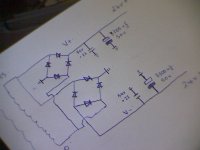
As your design requirement is for no wires across the floor, locate your satellite speakers each close to a power point. You could use two Toroidal 35 VAC transformers one at each power point and use 2x full wave bridge supplies ( 35 amp bridge rectifier blocks are recommended as easy to wire and reasonably priced ) at each location inside suitable casework which requires compliance to mains wiring standards and a fuse or circuit breaker on the active mains lead approx 800ma- 1amp. If this all sounds foreign, please ask back here at the forum. A supply like this will provide 24v DC +and - which indicates you could develop max wattage at 8 ohms as 24 watts. The 1875 provides its best performance at about 20 watts, which is of course dependent on volume level arriving at its input. See diagram:
Cheers / Chris
Attachments
Last edited:
If you want no wires on the floor you could just buy longer wires so you could route them by the ceiling. Then you could just paint them same color as your ceiling/walls. But if you bought receiver and transmitter you really should build lm1875 although it could be a little too powerful for those 12W sattelites (provided by your link)
- Status
- Not open for further replies.
- Home
- Amplifiers
- Chip Amps
- Chip amp to power surround sound satellites?