I don't follow: why not just use the built in mute? What are you trying to get at with this particular circuit? I am sure I am missing something here. . . . .


I swear I am still missing something. If you add a cap then you get a soft start to avoid turn on thump, or just an easier switch (afaik since I simply use the built in mute pin for everything)
Simply switching the RM pin directly should be enough of a mute circuit for the chip, right???? 😕
Simply switching the RM pin directly should be enough of a mute circuit for the chip, right???? 😕
dfdye said:Simply switching the RM pin directly should be enough of a mute circuit for the chip, right???? 😕
Yes, the LM3886 datasheet mentions the following
Pin 8 Open or at 0V, Mute: On
Current out of Pin 8 > 0.5 mA, Mute: Off
dydfe:
I had a quick noob question based on your comment
do you have simple schematic for implementing a de-thump using pin 8? Do we just put a cap in place of the switch after the Rm (22k)?dfdye said:If you add a cap then you get a soft start to avoid turn on thump
I don't follow: why not just use the built in mute? What are you trying to get at with this particular circuit? I am sure I am missing something here. . . . .
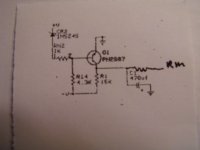
I believe it you attach this circuit where it says RM to the chip it will provide a means to control the voltage to mute the circuit or unmute it. It was just an idea because it would seem that all the circuit boards I have seen have RM soldered to the PC board and the chip comes on line when it is powered up and goes off line when it is powered down. When it is powered down with the RM resistor soldered to the board there is no way to mute the chip prior to shutdown and thus you have noise out your speakers on shut down. This small insignificant circuit would allow you to control the mute either automatically or manually. I was just an idea 😱
I had lots of fun with the muting pin when I built my active system a couple of months ago. The basic schematic suggests using a current limit resistor, a cap to ground, then Rm. This is great if you have a stand alone unit, but you have to be careful that the initial R/C are sized to charge/discharge within an appropriate timescale to avoid pops at both power on and off.
My problem came because I also had an active LR filter network running in the same box, and sizing the R/C to allow for its power up/down transients as well proved impossible, even after much fiddling with values. It just didn't turn off quickly enough. In the end, I used a relay to switch the -Ve to Rm, simply because I had a soft start assembly already in my bits pile, and it was easier than building something new. Thus, I think BF's design has some possible uses, much more elegant than my eventual solution. A nice slow start and a quick turn off is what we are looking for here.
My problem came because I also had an active LR filter network running in the same box, and sizing the R/C to allow for its power up/down transients as well proved impossible, even after much fiddling with values. It just didn't turn off quickly enough. In the end, I used a relay to switch the -Ve to Rm, simply because I had a soft start assembly already in my bits pile, and it was easier than building something new. Thus, I think BF's design has some possible uses, much more elegant than my eventual solution. A nice slow start and a quick turn off is what we are looking for here.
Al (pinkmouse) is the one who I first saw use this circuit, and based on his last comment, I think we know why the new circuit is getting circulated. If memory serves correctly, the original schematic is in the pinkmouse Super Sym 3886 PCB thread, but it was based on a National App Note.diarav said:do you have simple schematic for implementing a de-thump using pin 8? Do we just put a cap in place of the switch after the Rm (22k)?
Got it! Thanks for the follow-up for goofballs like me. I knew I was missing something. I (luckily) don't have any shutdown problems with my LM3886 based amps so I was just thinking soft-start, but I like the idea of muting prior to powering off.burnedfingers said:When it is powered down with the RM resistor soldered to the board there is no way to mute the chip prior to shutdown and thus you have noise out your speakers on shut down.
Member
Joined 2006
The muting function, that is adding in the 100 uF, should not have any soninc degradation, right? Thanks!
The problem with using the example mute circuit (from the datasheet) that consists of two resistors with a cap to ground between them, is that you have the same power up and power down delay. If you increase the power up delay, you also increase the power down delay. If you don't have any fancy input setup that requires a slow startup and fast shutdown, it's fine. And you can just use a switch to select either ground or the RC if you want mute functionality.
Member
Joined 2006
Thanks. Will swap in some discrete opamps in my electronic xo and see if the turn on/off transient is tolerable : )
- Status
- Not open for further replies.
- Home
- Amplifiers
- Chip Amps
- Chip amp mute circuit