bandwidth filters
Regarding bandwidth, I am grateful for the replies teaching me basic electrical engineering. I have been using the textbook " Practical Electronics for Inventors" ( Paul Scherz) to follow along, but this conversation is at an even higher level. I will have to find a more detailed audio reference text.
To avoid unintended consequences, leaving Rin and R2 unchanged ( changing R2 will require matching Rf, which changes the gain equation Gain = (1+Rf/R3), I came up with a starting point for the filters:
Low pass:
Fc=80K Hz C= 2nF R= 1k
High pass:
Fc= 2 Hz C= 3.6uf R=22K
I used this online calculator:
(Sample)RC Low-pass Filter Design Tool - Result -
Just commenting, reviewing the many schematics for Lm3886 amplifiers on diyaudio and elsewhere, it is difficult to " pick out" the filter networks, especially when some of the components are in the feedback loop fro pin three to pin 10. More to learn.
Charlie:
I will look at your projects.
The Lm3886 data sheet refers to a "Max supply voltage" which is dependent on the transformer regulation, and includes a Voltage "drop out" term of 4 volts (page 16):
Max supply voltage peak = +/- ( Vcc + Vod) ( 1 + regulation)
In my post I was just speculating on how to handle, or at least mathematically justify, a 22x22 transformer with 50% regulation, or an anticipated V DC of 33 volts. The chip is rated at 68 watts into 4 ohms at Vcc of 28. I am assuming I can subtract the Vod, 4 volts from 33 to attain the magical 28volts rail voltage.
Regarding bandpass, I expressed concern about changing resistance values of Rin and Rf affecting gain. ( Gain = 1 + Rf/R3). With some thought:
1. As long as I keep the ration of Rf/R3 the same ( currently 22k/680 ohms), I can change the value of both.
2. Low Pass Filter: Rin is currently 1k. Raising it to a value between 3k and 9K, I can use a Cshunt of 220pf to attain a Fc of 80-200k. Is it OK to experiment with Rin?
3. High pass filter. By lowering Rf between 22 and 15K, I can use a Cin of 1uf-10uf, attaining Fc< 15 Hz. Is there a limit, or an acceptable range, to the feedback resistor Rf?
4. I ran a spreadsheet to get these values. Reviewing many schematics, I see that Cshunt is usually 220pf, and Cin is usually between 1 and 10uf. I have tried to incorporate these values to find the possible resistor values noted.
5. can easily solder Cshunt to pins 9 and 10 of the chip. I have a choice with Cin: keep it as close to the PCB as possible, or solder it to the pins of the volume pot. The volume pot will be 6 inches away on average from the PCBs.
What is the best approach?
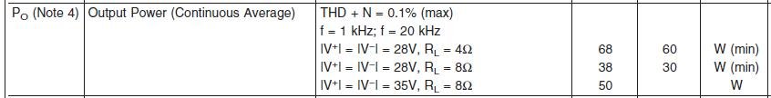
I refer you to the attached specification from the "Electrical Characteristics" table at the beginning of the datasheet.
The peak voltage formula is: Vpk= sqr root(2 * Power * resistance). If we plug in the values from the LM3886 datasheet for 4 ohms we have:
SQRT( 2 * 68 * 4 ) = SQRT( 544 ) = +/-23.32Vpk
Note that 28V - 23.3V is about 4.7V, which is more than the dropout voltage you mentioned.
The same goes for an 8R load:
SQRT( 2* 50 * 8 ) = SQRT( 800 ) = 28.3Vpk
where the rail voltage is recommended as 35V, or 6.7V "extra".
These calculations are for a resistive load. Note that a complex driver impedance that is "4 ohms nominal" can drop to below 4 ohms (typically around 3 ohms) and present a more difficult load than a simple resistive one. Don't push the rail voltages past the recommended values, especially with the TF version of the LM3886.
Attachments
an 8ohms speaker can demand three times the current that an 8r0 resistor would.................These calculations are for a resistive load. Note that a complex driver impedance that is "4 ohms nominal" can drop to below 4 ohms (typically around 3 ohms) and present a more difficult load than a simple resistive one.................
for 28.3Vac (50W into 8ohms) the peak resistor current is 28.3/8*sqrt(2) = 5Apk. This is well within the specified peak current for a cold to warm 3886.
This is how National hide the limitations of their chipamps. None of the other manufacturers are any more honest. Try to find some information on how the chip behaves/performs when Tj is >25°C
When driving an 8ohms speaker to that same maximum of 50W, expect peak transient current demand to approach and even exceed 15Apk.
This is where Chipamps fail. They cannot deliver these peak currents. I call them current crippled.
4ohms speakers are even worse. Their peak transient demands are higher.
Chipamps suit higher efficiency high impedance speakers. But not too high efficiency because then you notice that they are noisy.
Last edited:
an 8ohms speaker can demand three times the current that an 8r0 resistor would.
Andrew, just curious where you come up with the "three times" factor for current demand?
I agree with all your points on this one...
i guess he's thinking of resistance dipps thruout the bandwith of the speakers.
a 8ohm speaker kan have a 2.5ohm dipp in low frequences. Wich result in Extreme current demand.
a 8ohm speaker kan have a 2.5ohm dipp in low frequences. Wich result in Extreme current demand.
No, he's not.
I am referring to various reports that state that reactive speakers draw more current than the equivalent resistor would.
Many state from 1.5times to 3times.
Fairly recently there was a link to a report that stated > 5times for all three speakers tested. They published the results for actual music excerpts into actual speakers.
Based on earlier work I use 3times. Before that I used to check at 2times, but there was enough evidence to convince me that was too low.
No, he's not.
I am referring to various reports that state that reactive speakers draw more current than the equivalent resistor would.
Many state from 1.5times to 3times.
Fairly recently there was a link to a report that stated > 5times for all three speakers tested. They published the results for actual music excerpts into actual speakers.
Based on earlier work I use 3times. Before that I used to check at 2times, but there was enough evidence to convince me that was too low.
Ah I see now. You are talking "speaker" and I am talking "driver". A speaker includes the impedance of all drivers and the crossover network. I have seen some really dumb a$$ crossover networks where the impedance dipped below 1 ohm at some frequency, and had a significant phase angle at that frequency. Hello mighty designer did you not take electronics 101? So I suppose you are correct for driving speakers with seriously "difficult" loads.
That's what I thought and why I "tested/measured" my amplifiers into a half resistance load, i.e. for an 8ohms capable amplifier I EXPECT it to properly drive a 4r0 dummy load to almost the same voltage. Many of my amplifiers achieve better than -0.6dBV into 4r0 cf. 8r0.
Then I was seeing more and more advice that half resistance did not leave enough margin for severe reactance speakers. So I now test to 1/3rd of rated amplifier impedance and still expect nearly full output voltage.
But that report that I referred to chose a severe reactance speaker and a reputedly meium reactance speaker and a reputedly very benign speaker.
The test results using real music signals showed that all three speakers could in exceptional moments within the music draw more than 5times the current that a nominal resistive load would draw.
I am not ready to move to 5times. My 3times rule works for me at the moment.
- Status
- Not open for further replies.
- Home
- Amplifiers
- Chip Amps
- Chip Amp Build, Heat Sink and Power Calculations