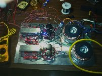
I have built a LM 3886TF 4 channel, 2 power supply amplifier from ChipAmp.com. On initial listening it sounds splendid, with good punch and crispness. There is no hum to be heard. In fact, I think it sounds better than the consumer Onkyo amp it will be paired with!
Each power supply has a 250 VA, 5 amp transformer. The transformer secondaries measure 25.3 V AC, and the output from the power supplies is 37.5 V DC. I picked these transformers to attain the output on the datasheet:
68 Watts at 4 ohm ± 28 V
50 Watts at 8 ohms ± 35V
At the moment the amps are feeding two pairs of 8 ohm speakers in parallel.With a little work in the attic, these speakers ( in ceiling type) will be the middle/rear speakers for a 7.2 system. So I have been interested in the power into both 4 ohm and 8 ohm.
My questions are about choosing heat sinks, DC offset, and power calculations in the 3886 datasheet.
The DC offset is 90 mV in two amps, and 107 mV in the other two. As noted, the sound is fine. Is it worth tinkering with the resisters to lower the offset? Of note, using an audio generator, a 94 mV input at 500Hz is uncomfortably loud.
The pertinent equations for the heat sink are, using 4 ohms as Rload :
PDMAX = Vcc2/2π2RL = 55.95 W
θSA = [Tjmax-Tamb)-PDMAX(θSA+θCS)]/PDMAX = 1.03 deg C/W. The max junction temperature used here is 150 deg C. At 8 ohms the thermal resistance is 3.26.
Thus, do I need a heat sink with a thermal resistance < 1.03 for 4 ohm loads?
These are hard to find unless they are gigantic, 12 inches long or so. I have found this:
43DN-01000-A-200 - H S MARSTON - HEAT SINK EXTRUSION | Newark element14 US, which has a thermal resistance of 1.5. I would like to put two 3886 chips on one heat sink, playing music at low to moderate levels. This should work fine with an 8 ohm load, at least, correct?
I performed power calculations to see if I've picked the right transformers.
At 4 ohms Vpeak os 23.32 V, I peak is 5.83 A and the max supply voltage is 31.55V. At 8 ohms Vpeak is 28.28, Ipeak is 3.53 and the max supply voltage is 37.44
At first glance does this mean the transformers are matched for 8 ohm loads, but too much for a 4 ohm, load, with the extra voltage converting into excess heat ? Would it be possible to use one transformer, of what size?
Construction of the device was done in a Hammond aluminum chassis. I followed the instructions on the chipamp.com website. The only difference is I put a copper 1/4 diam rod , 6 inches long, in the chassis. Earth ground and a ground lead from each power supply go to the copper rod.
I would like to measure the power used by this device. Is it safe ( and accurate) to use two DVMs to measure voltage and current at the speaker binding posts for the output measurement? Can the same measurements be done simultaneously at the inputs to the amps to measure current draw?
Because this is my first project requiring power generation, and I am very interested in the heat generated by the chips, I did a little experiment. I used a 4 inch block of aluminum as a a heat "reservoir". With just line power and no input, the chip and metal block rose from 27 to 40 deg C over two hours. Hooked up to very loud music, the chips and metal blocks rose to 70 deg C within 10 minutes ( this is with a 4 ohm load). This fact has made me wonder whether I have matched the transformers to the speaker load correctly.
Attachments
A1............... Is it worth tinkering with the resisters to lower the offset?
................ do I need a heat sink with a thermal resistance < 1.03 for 4 ohm loads?
................. This should work fine with an 8 ohm load, at least, correct?
...................At first glance does this mean the transformers are matched for 8 ohm loads, but too much for a 4 ohm, load, with the extra voltage converting into excess heat ?
.................Would it be possible to use one transformer, of what size?
.............. Is it safe ( and accurate) to use two DVMs to measure voltage and current at the speaker binding posts for the output measurement?
...............Can the same measurements be done simultaneously at the inputs to the amps to measure current draw?...............
Yes. Balance the +IN & -IN resistances.
A2.
I always recommend that you double the size of the heatsink that National recommend in the datasheet.
A3. ?
A4.
you either set up for 4ohms speaker, or 8ohms speaker.
A4.
the amplifier will work if the transformer VA is approximately 1times to 2times the total maximum output power. i.e. for two channels of 68W use a transformer with a VA from 136VA to 272VA. (160VA, 200VA & 250VA all fit within that range).
A5.
you can safely connect more than one measuring instrument at any time.
If you have a known dummy load and you measure the voltage, you can find the current and the power from the voltage measurement. You don't need an extra DMM to find power.
A6.
yes, you can measure the power rail inputs. You can measure them simultaneously. Can you read them simultaneously?
Thanks for the reply, AndrewT.
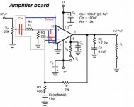
DC offset: By match the IN+/In- resistors you mean the 22K labelled on the schematic as R2 and Rf? By match you mean purchase several 1% tolerance 22K resistors and match the two closest in actual value?
2: Heat sink : I understand, pick the load impedance for the amplifiers, 4 0r 8 ohms. For this project, I have found , at HeatsinkUSA.com, large 8x2.9x3.94 inch heat sinks rated at 0.3 C.W per 3 inches. This will work at 4 ohms, where the calculated Osa was ,1.03, with 2 inches extra heat sink, for insurance.
In your experience, how how might I expect the ambient temperature within a non vented chassis to rise to? I will be measuring this: if it rises above a certain level, say 50 C, should I consider drilling vent holes in the top and bottom of the chassis.I only want to do this if necessary, for purely aesthetic reasons.
3. transformer selection. I understand 1X to 2X power requirement. In this project the transformers match an 8 ohm load the best. Repeating my question, using the existing transformers ( supplying 37.5 VDC), when 4 ohm load really only needs 31 volts, is the excess 6 volts presented to the chip converted to pure heat?
Furthermore, what exactly, sonically, do I get for using a quite large transformer, in this project 250VA. After hearing them I may hook them to my front speakers- the best quality in my house-and target a smaller 20W amp for the surround speakers.
4. measuring real time data. A dummy load could be a 4 ohm resistor across the speaker terminals? I have a few 10 ohm, 10%, 10 watt resistors i could put in parallel and have 5 or 3 volts as a the dummy load, plus extra power handling upto to 20 or 30 watts. Will this work or should I get an exact 4 ohm load? and yes, a voltage is all I need.
Real time measuring the input power- from the power supplies to the amps-, I can measure voltage from V+ to GND, but what is the resistance to use to find current? In FACT, I NEED THE impedance presented to voltage coming from the power supply, correct? which has both resistive and capacitive components? and is what in this circuit?
I have 2 DVMs available for measurement.
both at 22k +-5% is good enough.
The problem caused by many Builders is they change the resistance seen by the inputs by omitting the DC blocking capacitors or going very low in the feedback side to lower the noise.
If your heatsink is inside the chassis/box then you MUST have bottom and top ventilation to allow cool air flow through the heatsink.
Even with this ventilation internal temperature is higher than if the heatsink is external.
Don't use post4 schematic. Most of the very necessary "optional" components are missing.
The DC block on the input is missing. That changes the input resistance to 1k instead of 22k !!!!!!!!!
Thanks
Ventilation: would 2 rows of holes, 8 inches long, above and below the heat sinks, be sufficient? 3/16th holes 1/2 inch apart?
The design doesn"t have a DC blocking capacitor. I've seen this on other schematics: usually a 1 uf electrolytic, with positive toward the input, or away from the chip side of the capacitor. Is this corrrect
I built this without volume control but have found I need it. The blocking cap would go before or after the 25K potentiometer? At least I can make all these modifications at once.
Balancing resistors for DC offset. 5% tolerance at 22K is 1100 ohms, so you suggest resistors within 1100 ohms of each other?
You didn't answer about the dummy load. Is my suggestion OK, to put 10 ohm resistors in parallel?
LM3886: the effect of the compensation network Cc, Rf2 and C
I found the above post in the chip amp forum from 2012. Most of it is beyond me, though it does highlight other locations for blocking capacitors.
I can confirm the LM 3886 datasheet has at least one typo. The equation for Pdmax shows Vcc*2. It should be Vcc^2 ( Vcc squared). Once I realized that, the equations started to make sense.
That sounds like it might get hot inside. Build it and find out how hot....................Ventilation: would 2 rows of holes, 8 inches long, above and below the heat sinks, be sufficient? 3/16th holes 1/2 inch apart?
1uF electrolytic for a DC blocking cap sounds a nonsense. Use a plastic film and preferably a polypropylene. At this value the cost is quite low.The design doesn"t have a DC blocking capacitor. I've seen this on other schematics: usually a 1 uf electrolytic, with positive toward the input, or away from the chip side of the capacitor. Is this corrrect
The vol pot is NOT part of the amplifier, it is your Source. The DC blocking cap must separate the amplifier input from the SourceI built this without volume control but have found I need it. The blocking cap would go before or after the 25K potentiometer?
The input offset currents vary in any amplifier. I would not be surprised to see data that they vary by 10%. The ONLY way, I know, to find out what resistor values, each input needs, is to measure the amplifier and then adjust the input and feedback resistances appropriately...................Balancing resistors for DC offset. 5% tolerance at 22K is 1100 ohms, so you suggest resistors within 1100 ohms of each other?
I could not understand the question. I leave to another to unravel and give an answer.You didn't answer about the dummy load. Is my suggestion OK, to put 10 ohm resistors in parallel?
Last edited:
The National 3886 datasheet is riddled with misinformation.
The engineers and technicians could not have written this balderdash. Some hack was paid to write that and did it without proper checking of what he/she had written.
Maybe, now that Ti are in control they will check what is in the datasheets. I fear that will cost too much.
The engineers and technicians could not have written this balderdash. Some hack was paid to write that and did it without proper checking of what he/she had written.
Maybe, now that Ti are in control they will check what is in the datasheets. I fear that will cost too much.
I am waiting for parts to arrive, especially the new heat sinks.
I have one question. The DC blocking capacitor comes after the volume pot, which is part of the SOURCE.
Now does the blocking capacitor come before or after the 1K ohm part of the voltage divider with the 22k input resistor. Or, is the 1K resistor even needed with the blocking capacitor?
As I reason it, if the blocking capacitor comes before the 1k resistor then nothing has really changed: the amplifier chip sees a 1k and 22K resistors in parallel. However, if the blocking capacitor comes after the 1K resistor, then all the chip sees is the 22k, which then can be matched to the invert side of the chip. Does this make sense?
Most receivers have a pair of Passive bandwidth limiting filters built into the input.
I always recommend this arrangement to all less experienced Builders.
The DC blocking cap and the Rin resistor form the High Pass filter.
The series resistor and the following shunting cap form the Low Pass Filter.
The order that these two groups are placed does not affect the operation of either.
The order of the two components in each filter are absolutely important to the operation of the filter.
The apparent Voltage Divider is a consequence of placing Rin AFTER the series R. It does not have to be that way. Rin could be placed BEFORE series R.
low pass and high pass filters
Do I understand, you would like to see me create a high pass and low pass filter at the input.
This requires adding two capacitors.
The high pass filter is comprised of a new Cin and the 22K resistor to ground.
The low pass filter is the 1k series resistor and a new Cshunt bridging the +/- inputs on the Lm3886 chip.
Using a web site to perform the calculations, and the existing resistors, and choosing 20Hz and 20K Hz as the Fc points, a best fit for Cin is .35uF, and for Cshunt, .007uF where Fc = 1/2piRC
Please see the attached amended schematic.
Attachments
I performed power calculations to see if I've picked the right transformers.
At 4 ohms Vpeak os 23.32 V, I peak is 5.83 A and the max supply voltage is 31.55V. At 8 ohms Vpeak is 28.28, Ipeak is 3.53 and the max supply voltage is 37.44
At first glance does this mean the transformers are matched for 8 ohm loads, but too much for a 4 ohm, load, with the extra voltage converting into excess heat ? Would it be possible to use one transformer, of what size?
I don't think that anyone commented on this specifically, but your rail (DC) voltages are too high for a 4 ohm load. You mentioned that you were using two 8 ohms drivers in parallel. That's not a good idea if your supplies are 37.5 V DC. The "TF" version of the chip has a built in insulating coating. This makes it easy to work with but it has reduced heat transfer.
You should probably consider a transformer with a lower secondary voltage if you really plan to use the chip amps with 4 ohm loads.
The rtramsformers are Avel Lindberg 250 VA 25x25. I was expecting 31-32 volts DC , not 37.5.
With maximum peak supply voltage of the 3886 at 31.5 v into 4 ohms, there are two choices in the Avel Lindberg line.
At 160 VA, there are 18x18 and 22x22. At 230 VA there is an 18x18. the 22 volt secondary, might be just right, if the secondary DC voltage is indeed around 33 volts ( using a 50% regulation factor as in the transformers I have now). Any comments?
Why is 37.5 v high for 4 ohms? It seems what is necessary to get the maximum 68 watts of power advertised on the 3886 datasheet.
At any rate, my guess is there is excess voltage on the rails at 37.5 volts, which ends up dissipated at the chip as V^2/R power loss, reflected in how hot these chips rand in my initial tests. What do you think?
I don't mind buying smaller trannies. I'l use these larger ones for something else, if it comes down to that
Why is 37.5 v high for 4 ohms?
Short answer: The chip can not get rid of the heat at the rated (full) power and it will overheat even if it is mounted to a large heatsink.
You might want to review the LM3886 datasheet, page 17, "thermal considerations: heat sinking" and the table on the top of page 14. Note that if you use +/- 33VDC rails this is |V+| + |V-| = 66V. Its clearly above what they recommend. You can also see in the first Power Dissipation figure top left of page 14 that the dissipated power (heat given off by LM3886) quickly increases to 50-60W and all of this heat must be transferred to and removed by the heatsink, something that is not easy for the TF version even if you put it on a large heatsink. If the chip heats up too much, its thermal protection will shut it down. If you only need only 10W of power, then you might be OK because the dissipation will be low.
It's much better just to use lower rail voltages. You will need a different transformer. Typically people choose 21-22VAC for the secondary voltage for 4 ohm nominal loads, since that should give about 28VDC after rectification and smoothing by the caps. Keep in mind that the actual impedance of the speaker can be around 3 ohms for some frequencies even for a "4 ohm" driver.
Also, not sure what exact Avel transformer you are using, maybe the Avel Y236652? Note the primary voltage... Another snafu that may get you with that trafo is that the primary is rated at 115VAC but the local mains voltage may be more like 120VAC, about 5% higher, and this causes the DC rails to be about 5% higher too. Also, the "25+25" secondary might be the AC voltage on the secondary at the rated power (likely), or it may be the secondary voltage under no load. If it is the voltage at the rated power, then the no load voltage will be higher, probably by 6.4% (the rated regulation). You should plug in the transformer to your wall and measure the actual secondary AC voltage with a meter and then do a sanity check on all the above points.
Last edited:
That narrow passband range would not be acceptable to most builders/listeners.......... you would like to see me create a high pass and low pass filter at the input................ and choosing 20Hz and 20K Hz as the Fc points...............
Most would widen that at least one octave at top and bottom.
Manny would go at least two octaves wider.
Some would go a whole decade wider.
A few would go even wider still.
I suggest you aim for 5Hz to 80kHz as an absolute minimum (that's two octaves) and experiment out to 2Hz to 200kHz ( that's a full decade wider) and listen to the results.
THEN CHOOSE what suits you and your equipment and your room.
BTW,
K = Kelvin, a temperature measurement.
k = kilo = 10^3 multiplier.
All multipliers from 10^3 and lower are lower case.
All multipliers from 10^6 and higher are upper case.
That narrow passband range would not be acceptable to most builders/listeners.
Most would widen that at least one octave at top and bottom.
Manny would go at least two octaves wider.
Some would go a whole decade wider.
A few would go even wider still.
I suggest you aim for 5Hz to 80kHz as an absolute minimum (that's two octaves) and experiment out to 2Hz to 200kHz ( that's a full decade wider) and listen to the results.
THEN CHOOSE what suits you and your equipment and your room.
+1 on Andrew's advice here.
One reason for choosing wider corner frequencies has to do with phase. The phase change for a first order RC filter is very gradual. You don't want to change the phase within the 20Hz-20kHz range and moving the Fc two or more octaves away keeps the phase change that will occur within the passband down to 10-20deg or less.
Another reason is that the frequency response is down 3dB at the corner frequency for a first order RC filter and it also falls of "gently". You want to maintain a flat frequency response within the audio range.
power requirements
Thanks for replying, CharlieLaub and AndrewT.
The transformers are Avil Y236652. The same brand has a 22x22/160VA transformer that would, at 28V, supply a Pmax of 9 watts, requiring a heat sink with a thermal resistance of 12 C/W. This is the Y236503.
I did measure the unloaded secondary outputs, and they were 25V AC. I can only conclude that the Avil Lindberg transformers are regulated at 50%, when I get 37.5 volts DC from the power supplies. If the smaller transformers are also regulated at 50%, I will get 33 volt rail voltages. The datasheet says the Lm3886 chips consume 4 volts, so (33-4=29) is close to 28 volts.
Regarding Charlie's comments about the other graphs on the datasheet, I did recognize I was at the top of the ranges, at least. Once I realized that the ambient temperature in the chassis was going to be substantially above ambient, I was " off the chart" on the Thermal resistance chart on page 11.
Nevertheless, being new at this type on construction, and wanting at minimum, to learn from my mistakes, I constructed the amplifier using the materials at hand. Personally, I think the unit is a fire risk and can't be left on unattended today.
There are a couple of ways around your dilemma of power supply rails that are too high in voltage:
1. regulated rails - the voltage(s) are maintained at a fixed voltage
2. introduce some voltage drop into the system using a transistor and some circuitry on each rail
I have essentially combined 1 and 2 above in a project that I am working on - a capacitance multiplier with voltage limiting. There is a thread about it in the Power Supply section and I have some boards that I will be building and testing soon.
I posted a long description of some aspects of this circuit in another thread:
http://www.diyaudio.com/forums/powe...er-over-voltage-protection-2.html#post3749612
This might be something for you to consider for your amplifier project.
The datasheet says the Lm3886 chips consume 4 volts, so (33-4=29) is close to 28 volts.
Not sure what you mean by "consume". This amplifier can not drive the load to the rails - there is a minimum voltage differential on the output transistors that is about 2-3V typical for any amplifier as a result of the characteristics of the transistor itself. If the rails are at +/-X, the amp's output can only swing to +(X-2) and -(X+2).
Is that what you were referring to?
If so, you can not ignore the extra volts when calculating power dissipation by the LM3886.
- Status
- Not open for further replies.
- Home
- Amplifiers
- Chip Amps
- Chip Amp Build, Heat Sink and Power Calculations