Hi,
I needed a cheap simple subwoofercross-over to be build into an old PA amp and bought one in China. I have reverse engineered it to see if I understand it. It's been a long time since I made any active cross-overs so I am very rusty.
So if you feel like it, could you have a look and comment? I asked for the schematics, but the seller couldn't deliver 😀
Please note I did my best but I cannot guarantee I did not make any mistakes in drawing or reverse engineering. I haven't build it yet to make the reverse engineering simpler, so cannot comment yet if it even works. If you have any questions or think I did make a mistake and should check something, just let me know and I will obviously oblige.

Edit: as should be expected, I did do some work as well. 🙂 Fixed the resistorvalue at the output of the third stage from 6k8 to 68k (my own mistake in reading the value on the PCB).
First stage is a buffer I guess. I find the 10k resistors somewhat smaller than expected since we don't know what will be driving it, but I'm not an expert. I think I may have a 10uF MKT to replace the bipolar (I mean electrolitic...) capacitor.
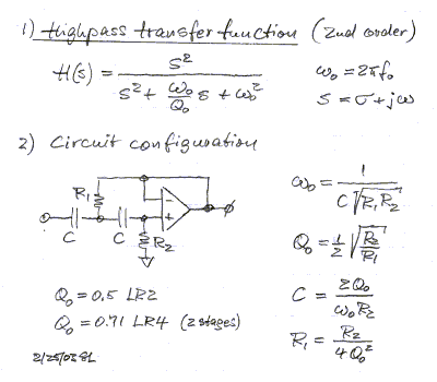
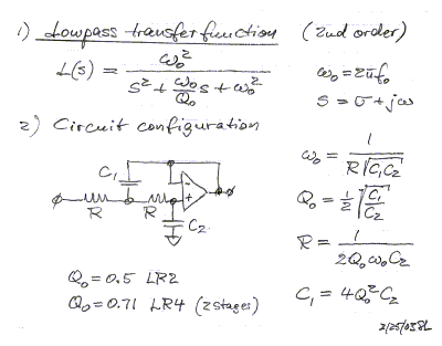
Found these on the website of Linkwitz Lab - Loudspeaker Design :

Second stage seems to be a 2nd order highpass filter. Frequency works out to be 49.8Hz (With R1 = 6k8, C=100n and R2=150k).
😕
Hope I messed up the calculation and that should be 5Hz?
Or more likely: 6k8 should be 68k and it would result in a nice 16Hz highpass! (Which adheres to a suggestion found elsewhere that R2 = 2xR1)
Fourth stage:

But I cannot work out how the potentiometer fits in exactly. I'll try to find some more info in old magazines, but for now I understand even less than two days ago when starting this post. 😀
I needed a cheap simple subwoofercross-over to be build into an old PA amp and bought one in China. I have reverse engineered it to see if I understand it. It's been a long time since I made any active cross-overs so I am very rusty.
So if you feel like it, could you have a look and comment? I asked for the schematics, but the seller couldn't deliver 😀
Please note I did my best but I cannot guarantee I did not make any mistakes in drawing or reverse engineering. I haven't build it yet to make the reverse engineering simpler, so cannot comment yet if it even works. If you have any questions or think I did make a mistake and should check something, just let me know and I will obviously oblige.

Edit: as should be expected, I did do some work as well. 🙂 Fixed the resistorvalue at the output of the third stage from 6k8 to 68k (my own mistake in reading the value on the PCB).
First stage is a buffer I guess. I find the 10k resistors somewhat smaller than expected since we don't know what will be driving it, but I'm not an expert. I think I may have a 10uF MKT to replace the bipolar (I mean electrolitic...) capacitor.
Found these on the website of Linkwitz Lab - Loudspeaker Design :

Second stage seems to be a 2nd order highpass filter. Frequency works out to be 49.8Hz (With R1 = 6k8, C=100n and R2=150k).
😕
Hope I messed up the calculation and that should be 5Hz?
Or more likely: 6k8 should be 68k and it would result in a nice 16Hz highpass! (Which adheres to a suggestion found elsewhere that R2 = 2xR1)
Fourth stage:

But I cannot work out how the potentiometer fits in exactly. I'll try to find some more info in old magazines, but for now I understand even less than two days ago when starting this post. 😀
Last edited:

Turns out the frequency adjust potmeter is NOT grounded in the schematic, but it IS on my PCB...
My assumption on the highpass not being 50Hz but 16Hz due to a wrongly printed value is wrong according to this schematic.
Any insights as to why it was designed like this? I could not (yet) find a better schematic as the PCB from this seller isn't available anymore.
Last edited:
- Status
- Not open for further replies.