Below is a spreadsheet capture using REW at various levels.
Reemember that the original unmoddified amp was producing over 3.5% THD at under 2watts so not a bad result I suggest, for minmal cost and effort.
1n across the 1k feedback resistor did nothing but 4.7n reduced the ringing to a negligible amount and reduced the edgyness of strings and the small amount off sibilance.
Last edited:
I don't know how much NFB you have in dB , but you should test how it sound with minimal , let's say 6dB , low distortion below a certain point is useless and will kill the sound
First of all you should tweak the cascode and the whole amp for minimum distortion without NFB so in the end you won't have to use that much
First of all you should tweak the cascode and the whole amp for minimum distortion without NFB so in the end you won't have to use that much
Last edited:
Latest measurements. Now seeing a mssive improvement in performance and extended listening yesterday was free of listening fatigue, no edgyness to strings, brass and no sibilance.
3rd harmonics are now below or equal to the 2nd, even at 10watts.

Max output for 1.2% THD is now a massive 10watts (8.6v RMS) at 1kHz, clipping is visible when going higher. Somewhat better than 2watts for 3% of the amp straight out of the box from which I would say the Chinese designer should be shot for spending no time optimising his/her design a for little extra cost.

I fitted a separate RC supply filter so each channel has it's own (4k7, 47uf) which has also improved the channel separation. (bottom table)
The 10K square wave is also much cleaner.

3rd harmonics are now below or equal to the 2nd, even at 10watts.
Max output for 1.2% THD is now a massive 10watts (8.6v RMS) at 1kHz, clipping is visible when going higher. Somewhat better than 2watts for 3% of the amp straight out of the box from which I would say the Chinese designer should be shot for spending no time optimising his/her design a for little extra cost.
I fitted a separate RC supply filter so each channel has it's own (4k7, 47uf) which has also improved the channel separation. (bottom table)
The 10K square wave is also much cleaner.
Schematic? The square wave looks much better than #61. I don't know if it was good out of the box we would not have learned anything.
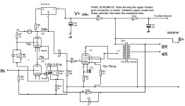
Final schematic.
SQ is excellent and had goose bumps all afternnon listening to my favourite pieces and also at much louder volume than normal.

SQ is excellent and had goose bumps all afternnon listening to my favourite pieces and also at much louder volume than normal.

Out of the box it was 2watts for 3% THD so I have learned much and was shocked that today I measured 10watts for 1.2% aand that is with the Chinese OPTs.Schematic? The square wave looks much better than #61. I don't know if it was good out of the box we would not have learned anything.
More screenshots atached. Changed the interstage coupling cap for a 47n PIO.
They were all taken at 8v RMS (8.8w into 7.3r dummy load).
A far cry from the premodded amp.


They were all taken at 8v RMS (8.8w into 7.3r dummy load).
A far cry from the premodded amp.
Attachments

Last edited:
I forgot to mention that Farnell Uk have a 100 or so of TO220 case !0M45 (~£5) and TME-UK have similar number of LR8 TO92 case.
I bought 10off these at 70p ea for an ECC88 preamp which has 10k & 56K anode resistors, both of which will be replaced with LR8s, one at a time after I have measured the design in standard form.
I bought 10off these at 70p ea for an ECC88 preamp which has 10k & 56K anode resistors, both of which will be replaced with LR8s, one at a time after I have measured the design in standard form.
bateryman,
Your schematic in Post # 65 and Post # 68 has an error.
Pin 4 on the output tube is not connected to anything.
An EL34 without the Screen connected to a positive voltage is unpredictable, or more likely, there is very little or no plate current.
Your schematic in Post # 65 and Post # 68 has an error.
Pin 4 on the output tube is not connected to anything.
An EL34 without the Screen connected to a positive voltage is unpredictable, or more likely, there is very little or no plate current.
Its connected to the UL tap, just couldn't make my schematic design prog let me connect it for some reason.
If I had the resources and the energy, I would put ALL Software companies out of business.
Stop accepting bad software.
Missing features
Broken features
Interface that only a programmer understands
Add your observations to the list.
Except software; do not Accept it.
Complain!
If you do not complain to the right people . . . you will always get bad software.
Doing the same thing over and over again, and expecting a different outcome is the definition of Insanity.
Just name me "Tired O. Software"
It was mainly down to operator error. I couldn't find an audio transformer symbol with a tap. I should have edited it and saved as a new package but didn't bother because I wasn't planning to make a pcb.
So after a few months, I noticed that the treble was sounding harsh again.
I checked the distortion again and was shocked but not surprised given the sound, that I couldn't get more than a couple of watts before all the distortion harmonics shot up to over 1%. No way could I get 8watts at all. Voltages and currents are unchanged.
I tried swapping the EL34s for KT77s but this made no difference (anode current was the same at about 70ma).
So what can have changed other than the PSvane 6SN7GTs?
I'm am building an Akido noval to replace the front end, using a 12AX7 for the input stage with a gain of about x30 and a 12AU7 output for low impedance drive to the EL34.
- Home
- Amplifiers
- Tubes / Valves
- Chinese EL34/6SN7GT SE Unusual Topology