I bought this ebay 'bargain' to drive the Scanspeak tweeters in my Naim SBL active system (driven from an IXO).
The component quality seems ok - Epcos and Nichicon capacitors and Psvanne tubes.
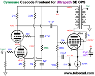
It barely makes 2watts before the distortion heads above 10% so I decided to draw out the schematic.. I hoping to see about 4watts at well below 10% thd. The mains transformer heating and low EL34 cathode resistor suggests that the poor performance may be due to the input stage.
So, given my limited valve knowledge, surely point x should I think be connected to 0v not to the cathode of the lower triode?
R7 should surely be connected to V+. not to the anode of U?
Also, R8 shouldn't be fitted as there seems to be a UL tap on the OT. I suspect some versions may have had a UL/triode switch so to save a few pence: they've just shorted out the switch connection points.
I haven't yet recorded the voltages.
The component quality seems ok - Epcos and Nichicon capacitors and Psvanne tubes.
It barely makes 2watts before the distortion heads above 10% so I decided to draw out the schematic.. I hoping to see about 4watts at well below 10% thd. The mains transformer heating and low EL34 cathode resistor suggests that the poor performance may be due to the input stage.
So, given my limited valve knowledge, surely point x should I think be connected to 0v not to the cathode of the lower triode?
R7 should surely be connected to V+. not to the anode of U?
Also, R8 shouldn't be fitted as there seems to be a UL tap on the OT. I suspect some versions may have had a UL/triode switch so to save a few pence: they've just shorted out the switch connection points.
I haven't yet recorded the voltages.
Attachments
Input stage seems to be cascode so it is made with 2 triodes one on top of another ...
2W in triode mode is low but what is the power dissipation , voltage across tube and current ?
I suspect the output stage is not well designed , for reference look in the EL34 datasheet how it is biased in triode mode
2W in triode mode is low but what is the power dissipation , voltage across tube and current ?
I suspect the output stage is not well designed , for reference look in the EL34 datasheet how it is biased in triode mode
Last edited:
Yes, thought it was cascode but have never seen the upper triode grid connected to the lower cathode and the upper divider resistor taken from the anode rather than V+. From what I have seen, the upper grid is usually biased to about 1/3rd V+ (maybe 100v) with a simple 2:1 divider from V+ to 0v.

Maybe it is made wrong but double check , of course you should see with a scope , without negative feedback , if at 2W (when is begining to distort) the input signal into EL34 is clean or not
If the EL34 is really configured that way then the loading of the tube and output transformer would both be a bit messed up. I would choose one or the other--either UL with the plate and screen separated, or triode-connected with the UL tap disconnected. Either way should improve performance.
Updated my schematic withcorrect resistor values and voltages.
I think the 6SN7s cathode resistors are too low - surely cathode needs to be a bit higher than 1.15v for a 1v rms input signal?
My plans are to replace the 68k anode load with a current source, connect point x to ground, and remove R3.
In the meantime I will do the above mods except the current source to one channel and compare with the other.
I have a pair of unused D3As which i might used instead of the 6SN7s but it's a major mod.
What's your opinon of the D3a versus the 6SN7s?
I might design a pcb possibly allowing for parallel output tubes if there is any interest,
 and after I have done more testing to get the best results.
I think the 6SN7s cathode resistors are too low - surely cathode needs to be a bit higher than 1.15v for a 1v rms input signal?
My plans are to replace the 68k anode load with a current source, connect point x to ground, and remove R3.
In the meantime I will do the above mods except the current source to one channel and compare with the other.
I have a pair of unused D3As which i might used instead of the 6SN7s but it's a major mod.
What's your opinon of the D3a versus the 6SN7s?
I might design a pcb possibly allowing for parallel output tubes if there is any interest,
Do you have the UL tap available on TR1. If so try it UL. I can pop it on LTspice later if you wish.
If you want to modify it , there are similar and lets say "reliable designs" that you could follow
https://www.tubecad.com/2021/05/blog0536.htm
https://www.tubecad.com/2021/05/blog0536.htm
Attachments
Yes the UL tap is connected (40%).
Thanks for offering to see what LTspice comes up with.
I am considering a LR8 high voltage current regulator in place of the 68k resistor and set for a higher current (3-5ma).
Thanks for offering to see what LTspice comes up with.
I am considering a LR8 high voltage current regulator in place of the 68k resistor and set for a higher current (3-5ma).
Thanks, I've come across a few.If you want to modify it , there are similar and lets say "reputable designs" that you could follow
https://www.tubecad.com/2021/05/blog0536.htm
Andrea Ciuffoli's D3 with current source is one design I might pursue, but using a LR8.
http://www.audiodesignguide.com/Ibridone/
The most important thing is to have a good output transformers ... without is pretty useless . That you should test first
The amp is quite well made but not so easy to modify without removing most ofthe components and starting again.
It sounds quite reasonable at average volume but strained at higher levels.

Yes, I might need to upgrade the OPTs but if I can get 4-5watts of low distortion power that should be enought to directly drive the Scanspeak 8r tweeters in my SBLs.

It sounds quite reasonable at average volume but strained at higher levels.
Yes, I might need to upgrade the OPTs but if I can get 4-5watts of low distortion power that should be enought to directly drive the Scanspeak 8r tweeters in my SBLs.
By removing R3, there was a significant reduction in THD:-
No R3 = 3% at 3.15w @1kHz, with R3 3.97%
At 10kHz. 2.9% without R3, with R3 3.8% .
With no R3, @ 1 and 10Khz, 4.3w = 4.2% THD and at 5.4w = 5% THD
At 100Hz, THD are around 0.8%
Swapped the 6SN7s over - same results.
So next step is to try LR8 current source and then maybe other brand of tubes.
No R3 = 3% at 3.15w @1kHz, with R3 3.97%
At 10kHz. 2.9% without R3, with R3 3.8% .
With no R3, @ 1 and 10Khz, 4.3w = 4.2% THD and at 5.4w = 5% THD
At 100Hz, THD are around 0.8%
Swapped the 6SN7s over - same results.
So next step is to try LR8 current source and then maybe other brand of tubes.
You shouldn't have R3 and the UL tap connected at the same time, so either R3 and no UL tap, or no R3 and connect the UL tap to the screen. So yes, your power increased and distortion dropped. You should be able to get 7-8 watts power, but perhaps the output transformer isn't capable enough. I wouldn't worry too much about THD. It's going to be 10% at full power with just about any SET amp.
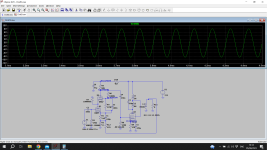
Just started simulating. So far the driver stage looks just fine as it is. Yes you can remove R3. The transformer you are using for a tweeter not whole range so its HF response that's important.
The distortion at 10k is the same as at 1kHz which is something I suppose. My hearing doesn't extend beyond 10k and the 2nd harmonic of course, is at 20k so inaudible.
I found some TO92 LR8 regulators for £1.60 delivered so that's my next mod, possibly with the current increased to 3-5ma.
I found some TO92 LR8 regulators for £1.60 delivered so that's my next mod, possibly with the current increased to 3-5ma.
Most of the distortion is in the output stage. You can remove the 470uF on the EL34 to see if that helps.
Thanks for taking the time to model this. What is the effect of not having C7? (not fitted at the moment so might be worth adding)
- Home
- Amplifiers
- Tubes / Valves
- Chinese EL34/6SN7GT SE Unusual Topology