I have this circuit.
LME49600: What is the closed loop gain of the LME49600 Evaluation Board design? - Audio forum - Audio - TI E2E support forums
Seems easy to mod to be VREF function:
Ground shortcut to -Vee
The DC Servo ref point and the OPA + to a VREF (2 red led-JFET based courent source feeded)
I Will do in the next decade :-D
now I'm lasy and don't want to build something completly new, so I'm considering to use my LME49600 + 49720 based DC coupled Headphone amp for avcc (at least temporary)
Any experiences?
That might work if they have a good linear +-15v power supply that doesn't get any digital junk picked up into it. Also you need a good clean low noise 3.3v reference to for the DC amplifier input. It should be on a clean power supply. Also, remember that you will need to set the amplifier gain =1 or the output will not be exactly 3.3v.
Last edited:
That might work if they have a good linear +-15v power supply that doesn't get any digital junk picked up into it. Also you need a good clean low noise 3.3v reference to for the DC amplifier input. It should be on a clean power supply. Also, remember that you will need to set the amplifier gain =1 or the output will not be exactly 3.3v.
Thanks for the thoughts.
I think this iswhy the q2m moddig was very useful. Everyone really learnt a lot.
I will apply those learnings which i gathered in the opa basd ref thread.(and basically what you summarized here)
Thanks again.
A good news i just discovered on this link it can be read there that the lme49600 is stable under any capacitive load.
The dac AVCC circuitry mostly looks resistive to the AVCC power supply. The large electrolytic caps ESS recommends to put at the output of an opamp buffer AVCC supply to not typically cause stability issues if the recommend capacitors are used. That's because the cap ESR and ESL increases rapidly as frequency goes up. Thus the caps don't look much like caps at high frequencies where they could cause AVCC buffer instability.
ESS recommends standard 47uf electrolytics, nothing special.
ESS recommends standard 47uf electrolytics, nothing special.
HI All,
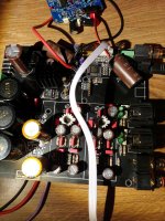
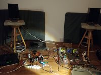
I managed to realize the AVCC REF circuit with LME49600.
I applied a simple TIP121 + LT431 based based stabilizer + CAP multiplicator,
A lot of CAP as filters everywhere.
The VREF are 2 LEDs feeded by 2SK170 based current source.
Finally I had to take out the DC servo (which was the part of the original headphone amp, because it caused issue, But not necessary - between the 2 sides there is <0.5mV diff.
Other changes:
- On the boeard the 2 AVCC line was separated
- the fake or not fake silmic CAPs are replaced with surely Silmic II.
- The filter OPA was reaplaced the LM49710
The sound is good. At least that quality already I had with the q2m.
(Onfortunately not able to compare - somewho the old DAC (q2m) since Christmas is out of order - something with the input part :-(

forgot to mention:
Tested with Hifiberry pro and CD (Arcam 7SE)
Tested with Hifiberry pro and CD (Arcam 7SE)
Attachments
Last edited:
That might work if they have a good linear +-15v power supply that doesn't get any digital junk picked up into it. Also you need a good clean low noise 3.3v reference to for the DC amplifier input. It should be on a clean power supply. Also, remember that you will need to set the amplifier gain =1 or the output will not be exactly 3.3v.
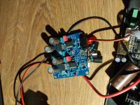
Finally i used a single side power supply for the lme79600. 5.6V.
Accordiing the datasheet both (the 49710 and 49600 works from 2*2.5V. (=5V single)).
The reason was that currently i don't apply any additional protection for overvoltage at the AVCC.
With this constuction the max output can be 4.7V. i hope it would survive this if it happens.
I was consdering a 3.6V zener, but i dnt know how much noise is generated if it is not in the avalanche phase yet. (Not open).
Any other idea?
I tested the circuit with a shotcky + tantalum if there is any starting spike - cant experienced .
(Still havent bought a scope :-( ).
Good Job.
I plan to use an lt3042 as reference voltage for the lm49600 and why not include the lm49600 in the regulation loop of the lt3042 (via the output sensing pin)
To measure the improvment i'm using a a usb sound card ( xonar u5) as input and usb xmos board with isolated spdif, I've got some measurements from a khadas tone board as reference, for now the es9038pro board is so far...
Im really curious on your results.
I have 2 3042 at home but without a board it is hard to solder in the air soldering style.
So the tl431 with several filtering is ok now. In the prereg.
As vref the LEDSs has extra low noise with tbe additional CAP filtering basically it is 0.
The 2sk170 fet has extra low noise as well.
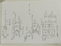
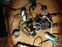
I enclosed the schematics
I have 2 3042 at home but without a board it is hard to solder in the air soldering style.
So the tl431 with several filtering is ok now. In the prereg.
As vref the LEDSs has extra low noise with tbe additional CAP filtering basically it is 0.
The 2sk170 fet has extra low noise as well.
I enclosed the schematics
Attachments
In addition i wanted to avoid this type of regs. I read several reports who said that in the voice line they are not really ok.
Changed last mile cabling to a high quality ofc with silver coating as short as possible.
Tried the zener as security device. Not good. 18mA with a 3.6V zener from 3.26V.
Later....
Consider8ng the Salas shunt behaviour with the current setup. 10.000uF on the board. Possible not good.
Destroys the Salas shunt quick response???
Will ask Sálas.
Tried the zener as security device. Not good. 18mA with a 3.6V zener from 3.26V.
Later....
Consider8ng the Salas shunt behaviour with the current setup. 10.000uF on the board. Possible not good.
Destroys the Salas shunt quick response???
Will ask Sálas.
Attachments
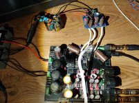
routing >5cm long wires over HF circuit perhaps is not the best solution regardless of silver coating... put the reg PCB underneath inverted and route 30-28AWG isolated wire through the elcap holes. 3.3V/50mA Nazars shunts for each channel with 22uF X7R on pins. take care of cooling though.
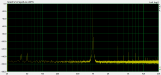
if you consider use a scope (>=100MHz) for validation of your power solutions, please remember that without correct measurement methodology this might be useless. a correct probe, something like this A wideband 1:21 1 kΩ DIY oscilloscope probe is pretty useful
if you consider use a scope (>=100MHz) for validation of your power solutions, please remember that without correct measurement methodology this might be useless. a correct probe, something like this A wideband 1:21 1 kΩ DIY oscilloscope probe is pretty useful
Last edited:
routing >5cm long wires over HF circuit perhaps is not the best solution regardless of silver coating... put the reg PCB underneath inverted and route 30-28AWG isolated wire through the elcap holes. 3.3V/50mA Nazars shunts for each channel with 22uF X7R on pins. take care of cooling though.
if you consider use a scope (>=100MHz) for validation of your power solutions, please remember that without correct measurement methodology this might be useless. a correct probe, something like this A wideband 1:21 1 kΩ DIY oscilloscope probe is pretty useful
I know it is terrible but I still don't have scope. (so I can mainly test with listening) and some with a higher resolution Multimeter.
(This is why I tested the transient with a Schotky + tantal on the output. - I know it is a terrible situation, but I spent all my money on the DAC and for other components (Silmic caps, etc...))
:-(
Clarified with Salas. The huge cap on the output is a wrong direction.
So the analog stage power is reorganized. Connected as close as possible to the board.
Removed big caps from the Salas reg output. Only 100uF at the OPAs.
Roughly 10000uF at the salas input.
Im shocked of the clarity of the voice! 🙂
My favorite CD Jazz at the pawnshop.
So the analog stage power is reorganized. Connected as close as possible to the board.
Removed big caps from the Salas reg output. Only 100uF at the OPAs.
Roughly 10000uF at the salas input.
Im shocked of the clarity of the voice! 🙂
My favorite CD Jazz at the pawnshop.
- Home
- Source & Line
- Digital Line Level
- China ES9018PRO ES9028PRO 9038PRO mods&upgrades