Hi All
I have this vintage valve radio from 1960s. It is powered on, and all other valves come on, but not the 5U4G.
How do I check if the 5U4G is faulty or something else could be wrong?
When it is taken out off the seat, I can hear rattling noise from the base. But the wires in the glass of the valve looks fine.
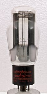
A lovely valve indeed.
Check for continuity between pins 2 and 8.
If there is continuity, the odd are that the heaters are intact so the issue is at the transformer eng. These use 5volt heaters and the heaters are at HT potential. Be careful!
If there is no continuity replace the valve.
A 5AR4 is similar as is GZ34 but there are lots of 5U4Gs out there. I probably have a few NOS ones that I use in my power amplifiers.
Attachments
Last edited:
I guess a 5U4G is cheaper and much easier to obtain than a GZ34/5AR4. The latter ones are the better tubes, though.
Best regards!
Best regards!
I did a continuity check on the pin 2 and 8, and there is continuity.
I plug the 5U4G back into the set, and powered on, but still no light.
But when I put ACV checking probe near the 5U4G while powering on the set, the probe was beeping with strong ACV indicating meter going up even from about 10cm away from it.
Which pins are to be checked for the output voltage? There are also 2x large bleeding resistors next to the 5U4G.
Measure the AC voltage between socket pins 2 and 8, but be careful with the HT voltage!! What does it read?
Best regards!
Best regards!
And the heaters don't light, although there's continuity? Then I guess your tube has drawn (much!) air. Does the envelope feel hot?
Best regards!
Best regards!
Not sure, if air has got into the tube or something is broken inside.
When it is pull out, there is rattling noise in the base.
Is there point reading the pin 4 and 6?
I don't think there will be HT 750V there. If there were, it would light?
The set is mute, as if nothing happening apart from other tubes light up when powered on.
When it is pull out, there is rattling noise in the base.
Is there point reading the pin 4 and 6?
I don't think there will be HT 750V there. If there were, it would light?
The set is mute, as if nothing happening apart from other tubes light up when powered on.
Measured the pin 4 and 6, and it went over 750 ACV, and then OL.
My DMM can read max. 750 ACV. It beeped loudly flashing OL.
My DMM can read max. 750 ACV. It beeped loudly flashing OL.
Changed over to my old Fluke 25 DMM from 1980s. It says it can handle upto 1000 ACV.
Powered the set on, and it read 1050 ACV between the pin 4 and 6.
1050 ACV? 😱
Powered the set on, and it read 1050 ACV between the pin 4 and 6.
1050 ACV? 😱
The noise from the socket says me a broken wire, arcing between them. Please, check the set using a current limited power supply like a filament bulb in series to one of the incoming line wires, possibly replacing the fuse.
The 5U4 draws 3Amper in the heater, so, a wire broken near the socket or the glass bulb will cause the two pieces of wire to arc. Tray heating the base pins with a well heated solder iron and entering some solder wire (Tin) inside them.
The 5U4 draws 3Amper in the heater, so, a wire broken near the socket or the glass bulb will cause the two pieces of wire to arc. Tray heating the base pins with a well heated solder iron and entering some solder wire (Tin) inside them.
The set has been powered on using the bulb current limiter with 60W bulb.
When powered on, it shows dim bulb light. There is not any type of fuse with this set.
There is good continuity between the pin 2 and 8, but there is no continuity between the pin 4 and 6. ACV between the pin 4 and 6 is 1050V.
When powered on, it shows dim bulb light. There is not any type of fuse with this set.
There is good continuity between the pin 2 and 8, but there is no continuity between the pin 4 and 6. ACV between the pin 4 and 6 is 1050V.
It is OK that there is no conduction between plates, else the tube is dead short.
Suggest the following: if yo have a DMM with AC ammeter, unsolder one of the heaters wire in the socket, and measure heater current. If the tube draws the nominal 3Amps, heater is OK and tube loos its vacuum. If no heater current or very different, then the tube has a problem in its heater. In any case, it seems to be defective.
Suggest the following: if yo have a DMM with AC ammeter, unsolder one of the heaters wire in the socket, and measure heater current. If the tube draws the nominal 3Amps, heater is OK and tube loos its vacuum. If no heater current or very different, then the tube has a problem in its heater. In any case, it seems to be defective.
Sorry, not exactly. If the vacuum has evaporated 😉, the heater/filament won't get to it's nominal temperature (won't light up), hence draw much more thanSuggest the following: if yo have a DMM with AC ammeter, unsolder one of the heaters wire in the socket, and measure heater current. If the tube draws the nominal 3Amps, heater is OK and tube loos its vacuum. If no heater current or very different, then the tube has a problem in its heater. In any case, it seems to be defective.
it's nominal current, hence heat up the envelope very soon.
Best regards!
Does this 5u4g then looks defective?
Is the heater current reading still be worthwhile?
To confirm, the pin 2 and 8 are the heater pins?
Is the heater current reading still be worthwhile?
To confirm, the pin 2 and 8 are the heater pins?
Certainly, but I believe the guy will understand me.Sorry, not exactly. If the vacuum has evaporated 😉, the heater/filament won't get to it's nominal temperature (won't light up), hence draw much more than it's nominal current, hence heat up the envelope very soon.
Best regards!
Does the 5U4 still have the silver getter flash on the glass or has it turned white?
That is the most obvious indication on the status of the vacuum.
Do you have a clear view on the filament wires? A 5U4 filament doesn't how very bright and is mainly hidden within the anodes, so easy to miss the glow.
That is the most obvious indication on the status of the vacuum.
Do you have a clear view on the filament wires? A 5U4 filament doesn't how very bright and is mainly hidden within the anodes, so easy to miss the glow.
The 5u4g glass is clear, and the wires clearly visible.
It is just rattling noise at the base inside gave me concern.
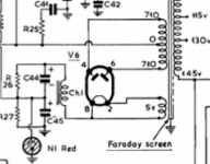
But the voltage on the pin 2 and 8 is 5v ac, and 4 and 6 is 1050v ac.
From the circuit daigram, I was expecting to read about 700v.
If it is still worthwhile I might do the current reading on the heater pin.
Another point is, that the set is not operational. Mute, even the other tubes lights up.
It is just rattling noise at the base inside gave me concern.
But the voltage on the pin 2 and 8 is 5v ac, and 4 and 6 is 1050v ac.
From the circuit daigram, I was expecting to read about 700v.
If it is still worthwhile I might do the current reading on the heater pin.
Another point is, that the set is not operational. Mute, even the other tubes lights up.
High voltage windings have usually, higher resistance, so surely the 700V you see in the schematic is under load, say, normal working; but with no set load, voltages increases.
If the rectifier doesn't heat its heater, then the rest of the set will not perform.
Don't you have another rectifier, or a couple os SS diodes to replace it temporarily?
If the rectifier doesn't heat its heater, then the rest of the set will not perform.
Don't you have another rectifier, or a couple os SS diodes to replace it temporarily?
- Home
- Amplifiers
- Tubes / Valves
- Checking tube - 5U4G