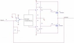
Has anyone used this topology before? ITs not a normal source follower (sources point towards the rails).. I left out paralleled FETS and components for stability to make the picture easier.
Has anyone had any major problem with this topology? I like it cause the output can swing really close to the rails ( @ Rail - FET turn on Voltage )
Give me your thoughts!
Has anyone had any major problem with this topology? I like it cause the output can swing really close to the rails ( @ Rail - FET turn on Voltage )
Give me your thoughts!
Attachments
I have a schematic with this topology and work very well and is very stable too.
At +/- 50V with a single HEX-FET pair run very well from 2 year into an active loudspeaker.
P=160W rms / 4 ohm with 0,1% THD.
I have made the supply for OP from power rail ( zenner stabilized)
and is no hum or other noise . My optim bias for this schematic is 60-90mA but run well at 150 - 200mA if it must.
This will only work with Source followers.
There is essentially no value to driving a Mosfet from a
darlington pair, as it's input impedance is very high. I
suggest dropping the Q2 and Q3. In fact, if it were me
driving from an opamp (which wouldn't be me at all), I
would drop the bipolar followers altogether.
Even if I did use a bipolar follower here, I would bias it
with a resistor from Emitter to Emitter, not to ground, as
this gives better performance.
If you are looking to swing rail to rail, connect the Sources
to the Rails, and take the Gate signal off the Collectors of
Q1 and Q4.
Sorry abou that. The N channel fet at the bottom SHOULD have the source pointing at the rail.
Since the sources dont point at the output and point at the rails this isnt a source follower. What would this be called Nelson?
I though the idea here was at 0 input the gates of the FETS should sit near rail (rail - bias). If the input goes high, Q2 should pull the gate voltage lower and lower and allow current to flow down though the FET. Then the opposite should happen to Q3 when the input goes negative.
Q1 and Q4 were for drive large banks of mosfets. I figure I would put the option of having them just in case.
The opamp is just a nice way to apply the voltage feedback. I thought this circuit seemed a little easier than a standard srouce follower cause you can get closer to the rails and need less pre-amp.
When the gates of the Mosfets are driven with the same
polarity of voltage, as here, then either both their Drains
or both their Sources need to attach to the output or they
will argue with each other.
polarity of voltage, as here, then either both their Drains
or both their Sources need to attach to the output or they
will argue with each other.
I created something similar tonight that worked well and was stable and stayed cool into 4 ohms. I did use an OPAmp 🙄 :
TL072 with +- 15 regulated setup to swing 14.3 V (any higher gave unacceptable amounts of distrotion) This fed into OPS of 2SK1529/2SJ200 biased with 2 SMALL red leds. Drains connected to rails, Sources forming output. The TL072 Voltage stage was capacitor coupled with .47uf between the two diodes to block faint hum coming from the OPAmp when there was no input. The OPS rails were 20V regulated ala Zen V2.
I also tested with IRF540/9540. Same setup except for bias. There I used 2 medium green and 2 medium red Leds: GR-R-R-GR with the capicator between the two red leds. this worked but ran hotter so I didn't run it for long as I figgured that using the IRF devices would need thermal compensation, I really designed it for the Jap. Mosfets.
Anyway; power out at 1kHz sine = 12W @ 8ohms, 25W @ 4 ohms
13 mV offset
Didn't sound too bad for a simple little circuit. As good or better than my AIWA chepie stereo. 'sides it was more of a prototype for working with this OPS.
-D.
Dozuki said:Didn't sound too bad for a simple little circuit. As good or better than my AIWA chepie stereo.
WAY more fun than any bought stereo too, no matter what the price. You could always try a higher voltage opamp like an OPA551. They look very nice on paper, and you can use + / - 40 v rails on them. That would certainly make your mosfets pull out into the fast lane 😎
GP.
Definately more fun 🙂 Since posting I've played more with the circuit and have the little TL running a 20V swing (without clipping) essentially doubling the power. I also changed the biasing diodes to a Vbe multiplier as this makes adjustment of Iq have more control as well as better control of X-over distortion. I'll look into the OPA551 as this would be a fun 'little' amp.
-D.
P.S. when I get done this one is gonna replace that AIWA, it has nasty hiss and my OP circuit is DEAD quiet.
-D.
P.S. when I get done this one is gonna replace that AIWA, it has nasty hiss and my OP circuit is DEAD quiet.
When sources are connected to rails, and output to drains, Miller effect causes a low impedance at the gates at high frequencies, and affects the linearity of the amplifier, because Cdg is a kind of varicap. This is why it is necessary to use emitter followers to drive the gates, with low impedance. Otherwise high frequency response is poor, and unsymmetrically distorted.
But another good (better?) solution is to use conventionnal design with sources at the output, and distinct power supplies for the driver stages, with some higher voltage, say 30% higher. Zener overvoltage protection on the gates is recommanded !
Regards, Pierre Lacombe.
But another good (better?) solution is to use conventionnal design with sources at the output, and distinct power supplies for the driver stages, with some higher voltage, say 30% higher. Zener overvoltage protection on the gates is recommanded !
Regards, Pierre Lacombe.
commons source output
I recall off the top of my head that in the 80's, Prof Cherry
published a paper in the Jaes that showed the common
emitter as a better output stage than an emitter follower.
I did not understand all the math, but I did remember
the conclusion above. It struck me as something rather
'unconventional' considering that most people use an
emitter follower. Feedback is required of course, to
get the output impedance to be low enough.
Yv
- Status
- Not open for further replies.
- Home
- Amplifiers
- Solid State
- Check out this FET Topology