Not quite sure where to put this question. I've not used an oscilloscope before and bought myself a basic picoscope. I'm using it to check wiring of an input transformer, which is an Audio Note "DAC 4".
If I recall correctly this can be used to convert between balanced and single-ended. One side has red, green, black wires and the other yellow, blue.
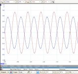
I set up the picoscope waveform generator with a sine wave, 1Khz, 1V and measured the same, which shows on the picoscope as 1.88V pp, nice sine wave but I guess dropping some voltage through resistances. All probes for this exercise were set to x1.
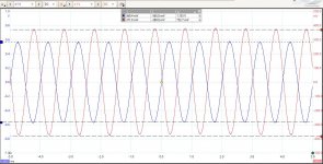
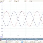
With the input applied across yellow/blue, attached is the output measuring across each half of the output (A = Red to Black, B = Green to Black). Nice out of phase sine waves, but there's quite a difference between the amplitude of the two ? Looking at the scope measures at the bottom of the screen, adding A and B peak-to-peak gives more or less the input peak-to-peak, allowing for error. I'm concerned this transformer isn't accurately centre-tapped and by using it I'll distort the signal.
Is this likely to just be instrument inaccuracies (picoscope, probes) or am I doing something wrong (being a self-confessed scope newbie).
If I recall correctly this can be used to convert between balanced and single-ended. One side has red, green, black wires and the other yellow, blue.
I set up the picoscope waveform generator with a sine wave, 1Khz, 1V and measured the same, which shows on the picoscope as 1.88V pp, nice sine wave but I guess dropping some voltage through resistances. All probes for this exercise were set to x1.
With the input applied across yellow/blue, attached is the output measuring across each half of the output (A = Red to Black, B = Green to Black). Nice out of phase sine waves, but there's quite a difference between the amplitude of the two ? Looking at the scope measures at the bottom of the screen, adding A and B peak-to-peak gives more or less the input peak-to-peak, allowing for error. I'm concerned this transformer isn't accurately centre-tapped and by using it I'll distort the signal.
Is this likely to just be instrument inaccuracies (picoscope, probes) or am I doing something wrong (being a self-confessed scope newbie).
Attachments
Last edited:
Is there a screen wire?
Is there a connection from can to chassis?
Neither
Then be careful with interference pickup.
Yes thanks, placement and shielding important.
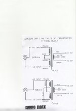
The AN DAC4 is silver-wired I believe, but there's no connection for shield. I also have a pair of AN silver line matching transformers (TT7692 BLUE) which DO have shields. They are in the prototype amps but I think I'll swap them over.
AUDIO NOTE TT7692 BLU
x RhythMick
Hi,
I also have a pair of these Audio Note TT7692 BLU transformers.
I have never been able to use them due to lack of technical data.
I would be infinitely grateful if all you have as technical information of these transformers would publish it here.
Thank you
x RhythMick
Hi,
I also have a pair of these Audio Note TT7692 BLU transformers.
I have never been able to use them due to lack of technical data.
I would be infinitely grateful if all you have as technical information of these transformers would publish it here.
Thank you
AUDIO NOTE TT7692 BLU
x RhythMick
Hi,
I also have a pair of these Audio Note TT7692 BLU transformers.
I have never been able to use them due to lack of technical data.
I would be infinitely grateful if all you have as technical information of these transformers would publish it here.
Thank you
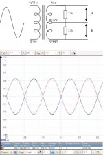
Attached is the diagram kindly provided to me by Peter Qvortrup of Audio Note.
Attachments
")
- Status
- This old topic is closed. If you want to reopen this topic, contact a moderator using the "Report Post" button.
- Home
- Source & Line
- Analog Line Level
- Check my measurement of Input Transformer pls