SOLD OUT . . . . SOLD OUT . . . . SOLD OUT . . . . I HAVE NO MORE KITS TO SELL
SOLD OUT . . . . SOLD OUT . . . . SOLD OUT . . . . I HAVE NO MORE KITS TO SELL
I've got quite a few kits of all parts + two sided PCBs to sell, for rev.3 of CheapoModo. The design is discussed in some detail, in another thread. Here in "Vendor's Bazaar" I am offering the kits for sale.
A full bill of materials is attached, showing my costs. I am selling each kit ("free" shipping is included), for
Please feel free to compare my costs (in the BOM) versus the prices above, to decide whether it's a good deal.
For those who wish to build CheapoModo Rev.3 themselves, I've included the CAD "Gerber files" that you can send to your favorite Chinese PCB fab, and get your own boards made. Then you can use the BOM to order parts yourself, from DigiKey or another supplier. PCB size is 35mm by 45mm. The Gerbers are in a zip archive attached to this post, named "cmodo_r3.zip". You can have them for free, I hereby place them in the Public Domain.
If you'd like to purchase a kit, please send me a Private Message indicating whether you'll pay by check (USD denominated checks drawn on USA banks only, please) or by PayPal. Then I'll send you my mailing address or my PayPal userId.
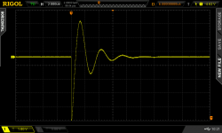
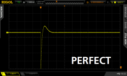
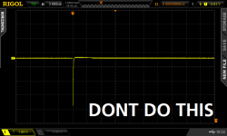
Rev.3 includes a new 33pF speedup capacitor, which slightly improves the risetime on the crucial FETGATE node. The waveform shows the textbook classic "Miller Effect" when the gate of a MOSFET is trying to rise, at the same time its drain is falling quickly. Schematic is below.
edit- US Postal Service just changed their fees and policies for shipping outside the USA. This increases shipping costs by $6.00 per CheapoModo kit, and I have adjusted the price list above to include these new, increased, postage fees. I apologize for the shocking and embarrassing high cost of shipping internationally.
_
SOLD OUT . . . . SOLD OUT . . . . SOLD OUT . . . . I HAVE NO MORE KITS TO SELL
SOLD OUT . . . . SOLD OUT . . . . SOLD OUT . . . . I HAVE NO MORE KITS TO SELL
SOLD OUT . . . . SOLD OUT . . . . SOLD OUT . . . . I HAVE NO MORE KITS TO SELL
I've got quite a few kits of all parts + two sided PCBs to sell, for rev.3 of CheapoModo. The design is discussed in some detail, in another thread. Here in "Vendor's Bazaar" I am offering the kits for sale.
A full bill of materials is attached, showing my costs. I am selling each kit ("free" shipping is included), for
Code:
USD 10.00  if pay by check     and ship to USA
USD 13.00  if pay by PayPal    and ship to USA
USD 21.00  if pay by USD check and ship outside USA
USD 24.00 if pay by PayPal and ship outside USAFor those who wish to build CheapoModo Rev.3 themselves, I've included the CAD "Gerber files" that you can send to your favorite Chinese PCB fab, and get your own boards made. Then you can use the BOM to order parts yourself, from DigiKey or another supplier. PCB size is 35mm by 45mm. The Gerbers are in a zip archive attached to this post, named "cmodo_r3.zip". You can have them for free, I hereby place them in the Public Domain.
If you'd like to purchase a kit, please send me a Private Message indicating whether you'll pay by check (USD denominated checks drawn on USA banks only, please) or by PayPal. Then I'll send you my mailing address or my PayPal userId.
Rev.3 includes a new 33pF speedup capacitor, which slightly improves the risetime on the crucial FETGATE node. The waveform shows the textbook classic "Miller Effect" when the gate of a MOSFET is trying to rise, at the same time its drain is falling quickly. Schematic is below.
edit- US Postal Service just changed their fees and policies for shipping outside the USA. This increases shipping costs by $6.00 per CheapoModo kit, and I have adjusted the price list above to include these new, increased, postage fees. I apologize for the shocking and embarrassing high cost of shipping internationally.
_
SOLD OUT . . . . SOLD OUT . . . . SOLD OUT . . . . I HAVE NO MORE KITS TO SELL
SOLD OUT . . . . SOLD OUT . . . . SOLD OUT . . . . I HAVE NO MORE KITS TO SELL
Attachments
-
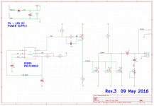 CheapoModo_rev3_schematic.png27.1 KB · Views: 2,283
 -
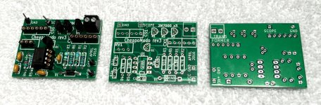 PCB_photo.jpg453.4 KB · Views: 2,248
 -
Bill_Of_Materials.zip6.4 KB · Views: 558
-
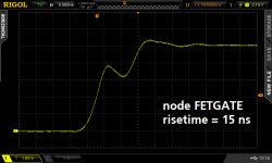 FETGATE_risetime.png23.2 KB · Views: 2,147
 -
 Begin.png30.4 KB · Views: 2,023
 -
 Almost.png27.8 KB · Views: 2,006
 -
 Done_Zeta_equals_1p00.png24.3 KB · Views: 847
 -
 DONT_DO_THIS.png24.2 KB · Views: 931
 -
cmodo_r3.zip19.4 KB · Views: 428
Last edited:
Eagle-eyed kit buyers have noticed that the color-codes of two resistors I shipped in the kit, do not match the resistance values on the schematic! How could this happen? And why?
The answer is, on the schematic I specified resistors from the E24 (5%) series of standard resistances. But when I purchased resistors to make up the kits, I decided to buy 1% metal film resistors, some of which are only available in the higher precision E48 and E96 series of values.
This occurred twice in the Cheapomodo Rev3 schematic
Electrically this is not a problem, the Cheapomodo circuit design is not sensitive to 5% perturbations in resistance values. But purchasers wanted reassurance and here it is.
I recommend kit buyers and other builders use their Digital MultiMeter to double check the resistance of each resistor before stuffing and soldering. This protects against mistakes when reading the color-code, and since there are only six resistors on the board, it only adds two minutes to your total build time. Cost=low, benefit=high: easy decision.
The answer is, on the schematic I specified resistors from the E24 (5%) series of standard resistances. But when I purchased resistors to make up the kits, I decided to buy 1% metal film resistors, some of which are only available in the higher precision E48 and E96 series of values.
This occurred twice in the Cheapomodo Rev3 schematic
Code:
R1   schematic says 6.8K    resistor in kit has color code 6.81K
R3 schematic says 910R resistor in kit has color code 909RI recommend kit buyers and other builders use their Digital MultiMeter to double check the resistance of each resistor before stuffing and soldering. This protects against mistakes when reading the color-code, and since there are only six resistors on the board, it only adds two minutes to your total build time. Cost=low, benefit=high: easy decision.
No, I've begun to think it's better to encourage members to try new things; to learn, to grow. So I make the Gerber CAD files available for free, to find them, read post #1 and post #132 of the Cheaponodo thread; members can send these Gerbers to a PCB fab house and get boards made themselves. This achieves two good results: (A) they get the boards they want; (B) they learn how easy and not-at-all-frightening it is to order PCBs.
Similarly for complete kits of all parts. I choose to provide a parts list, and members get the experience of ordering components from Mouser or DigiKey or another source, themselves. They receive the parts AND they get the experience of ordering parts themselves. Experience which will benefit them on all future DIY projects.
To my surprise, occasionally a member with entrepreneurial spirit will order a number of boards and/or parts, then resell them at a price of their own choosing. To find out whether anyone happens to be in this business today, you go to the main thread (not the Group Buy thread) and post a message saying "Does anybody have a Board X to sell?" or else "Does anybody have a complete kit of all parts including PCB, for Project Y, that they would sell me?"
I love it. I might be your next enthusiastic member willing to do a board run. 🙂
Learning board layout/design/creation is next on my list!
--Tom
Learning board layout/design/creation is next on my list!
--Tom
Hello Mr. Mark Johnson.
First of all, apologize for my lack of knowledge.
I have made this Cheapomodo Rev3 version in the protoboard, with the variant of using the BC546 transistor instead of 2N3906 and TLC555ip, instead of the SE555.
The problem I have is that I am unable to visualize the forms of waves with the oscilloscope, in order to make the appropriate corrections, the adjustment of the oscilloscope is in 1 volt and the time in 2000us, and I do not see anything, as if I had the disconnected probe .
Could you help me how I have to configure the oscilloscope to see the signals?
Thanks in advance.
Regards
Juan
- Home
- Vendor's Bazaar
- CheapoModo: a very cheap PCB that optimizes transformer snubbers