Having a couple of bags of NPN and PNP small signal transistors left over from a non audio project, I wondered what an amp made of just small signal transistors would work like.
Here is the working circuit, its not been simulated 😀 but sounds OK.
I'd recommend keeping the voltage down to +-12V. Its horribly inefficient due to the emitter resistors.
Perhaps its only saving grace is its cheap! at a penny a transistor semiconductors are less than one decent output device😛
I will probably make the stereo pair and use for a PC Amp - sounds better than the current low power chip amp..
Alan
Attachments
Last edited:
It is not that inefficient! All those parallel transistors can be considered as single ones with 0.5 Ohm emitter resistors and 20x the max current of a single transistor.
You can also drive it with higher supply voltage, depending the Vce_max of the transistors.
You can probably beef up the driver stage though!
I did simulate it, you can also probably fine tune it with simulations.
This looks and sounds like fun!
Peter
You can also drive it with higher supply voltage, depending the Vce_max of the transistors.
You can probably beef up the driver stage though!
I did simulate it, you can also probably fine tune it with simulations.
This looks and sounds like fun!
Peter
Last edited:
How about a het sink? Besides improved power, I would think the outputs should be thermally coupled together, since one could turn into a hot spot> my 2 cents....
I like the circuit board!
You could even parallel a bunch of TO-220 size transistors and they would fit in the same holes as the TO92.
Good job on the circuitry work!
You could even parallel a bunch of TO-220 size transistors and they would fit in the same holes as the TO92.
Good job on the circuitry work!
Thank you for the kind words.
I've attached the PCB layouts for anyone interested. These are set at 300DPI and are mirrored suitable for toner transfer.
A note on the input board. This is a generic one I use for lower power amps and has extra pads for a pair of emitter resistors when used with Power transistors. Add two emitter resistors and a pair for TIP 41/ 42 for a low power amp (10-20 watt) for example.
sregor, My thoughts, It gets warm! when running sinewaves at a few watts Never had the nerve to to run with higher than +- 15V as I can see it frying 😱 Staggering the transistors would help as in the board they butt against each other which can not help.
Attachments
Last edited:
Resistor + diode for Vbias driving a BJT output stage is not clever !
Maybe not 😉 but it works (and is stable) and this is a test unit to see if it works, it dose. It could be made fancy, improved in many ways without doubt. but that was not the original intention 😉 sorry if offends...
There is nothing to prevent anyone using other biasing arrangements ( just the resistor actually works fine) but there is no heatsink to strap thermal compensation transistors to at the moment. That would make life easier
alan
Last edited:
Sure it works and is stable.
The issue is very simple.
Underbiased, with one diode for instance, is giving crossover distortion and is perfectly stable.
Biased to avoid crossover distortion makes it potentialy unstable with possible thermal run away.
A very simple dilemna. Pick your doom.
The issue is very simple.
Underbiased, with one diode for instance, is giving crossover distortion and is perfectly stable.
Biased to avoid crossover distortion makes it potentialy unstable with possible thermal run away.
A very simple dilemna. Pick your doom.
Interesting project - I would use devices in the long TO-92 package for a bit more power dissipation. MPSW06 and MPSW56 are obvious first suspects that may be relatively easy to get. There are lots of Japanese devices in that package, too - a couple that come to mind are 2SA965 and 2SB2235, a pair of complementary devices I've used as drivers. About 1/2W per package (without forced air) is about the reasonable limit for the long TO-92 package.
Last edited:
thank you for the comments. I thoroughly agree it needs a better bias (and thermal compensation.
the testing bias was 5ma per transistor and no visible crossover distortion showed on my scope which is encouraging.
I do agree it needs better devices for real use. I was thinking the MPSA06 /56 or possibly the 2n5551 and 2n5401 as both are good value (between 5 to 10p each in 100 lots in the UK)
The driver transistors need to be from those types as well I think.
Then change the layout to allow a clamping bar to a heat spreader with the thermal bias compensation. Looks like I'll have a load of 2n2906 and 2904 again 🙁 once I rebuild
alan
One item of interest there appears to be very little /no noise perhaps because of the parallel transistors.
the madness continues...
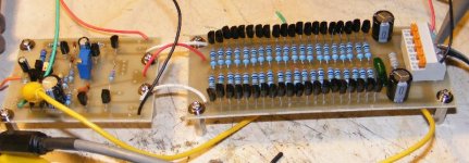
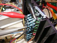
to follow up encouraged by the original test I've changed the outputs to 2n5551 and 2n5401 along with the drivers, the thermal compensation is 2 diodes on the heatsink now.
heatsink is a 5mm slab of ali with to92 sized holes in it bolted to a finned heatsink with thermal paste, the transistors are fitted in the holes with more thermal paste. Bias set to 50mv (5ma) per transistor
This works, running on +-30V lab supply it drives 20watts rms (1khz) into 6.8ohms (need to find an 8 ohm load) 😉 at the clipping point. The sink gets hand hot over 20mins.
With audio its clean. sounds OK.
On item of note the transistors are faster than the usual outputs, 100mhz plus for these examples and care is needed to stop parasitic oscillation. It would probably make a HF amplifier...😀
Attachments
Update
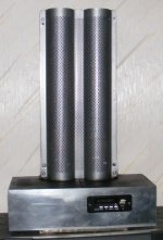
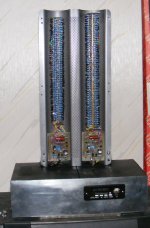
The SSTA (Small Signal Transistor Amp)
Well encouraged by the little amp which has been reliable. I've expanded it to 100 transistors per channel. This has now taken over as my PC amp.
The black unit in the front is a cheap remote control / MP3/FM/Line input unit so you could call this an integrated amp 😛 Its handy.
Transistors
NPN = 2N5551
PNP = MPSA92
10 ohm Emitter resistors
bias 10ma per side ( 0.1ma per transistor)
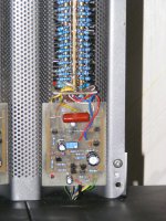
The transistors are chosen to allow a wide voltage range - Currently running +-20V When I get a higher voltage transformer I'll change and test. Its fine on +-30 from my lab supply.
If building one make sure you have zorbel networks in place, The bandwidth is very high and it can oscillate if you are not careful.
The casing is to keep fingers out!
Alan
The SSTA (Small Signal Transistor Amp)
Well encouraged by the little amp which has been reliable. I've expanded it to 100 transistors per channel. This has now taken over as my PC amp.
The black unit in the front is a cheap remote control / MP3/FM/Line input unit so you could call this an integrated amp 😛 Its handy.
Transistors
NPN = 2N5551
PNP = MPSA92
10 ohm Emitter resistors
bias 10ma per side ( 0.1ma per transistor)
The transistors are chosen to allow a wide voltage range - Currently running +-20V When I get a higher voltage transformer I'll change and test. Its fine on +-30 from my lab supply.
If building one make sure you have zorbel networks in place, The bandwidth is very high and it can oscillate if you are not careful.
The casing is to keep fingers out!
Alan
Attachments
Last edited:
- Status
- Not open for further replies.
- Home
- Amplifiers
- Solid State
- cheap transistor Amp