Yes, a cathode resistor will give local DC feedback (reducing operating point variability), as well as adding local AC feedback.
Member
Joined 2009
Paid Member
only simulation freaks worry about picking sweet spots where nth order distortion magically disappears.
Funny you mention this - I recall one poster who claimed that a design I was using had 20% THD (!) in his 'simulation'. However, real-world measurements showed THD to be less than 1%. Nothing replaces a measurement...
To be completely honest, I completely forgot about this thread. Since then I have gone back to simple resistor bias on that stage (accounted for in RIAA correction). I tried the low current LED's but they all seemed to color the sound more than the cheap red's. Some IR LED's were good as well, but I never found any neutral sounding low current LED's.
Battery bias (of the cathode) also coloured the sound, but battery bias of the grid is however something I still use in certain instances.
Ian
Last edited:
I use usually a 6n2p-eb (as mu-follower and resistieve load) with a bulk cheap chinoise red led (driver) and (phono) IR one. I think the activation through more mA (the resistor trick) is not necessary. It works with only about 0.5 mA and the sound is very fine. I like it.
Cheers
Cheers
I have tried low current LED's with decent success but some don't work as good as others. I ended up just using a resistor off the B+ to keep the LED in conduction. I don't think it's a good idea to run the LED right on the conduction knee.
You are right. All leds are not the same. I´m surprised and perplexed with those cheap diodes and low current. Others don´t work well: knee region.
Cheers
Cheers
Last edited:
I sometimes see this thread coming back to haunt me. Anyway, in the meanwhile I have tried some IR LED's for different applications that are also not bad at all.
I also had some cheap green LED's that were fairly decent in biasing 6SN7's.
But on the whole I have seriously gone back to resistors for bias. Decent films are just fine, bypassed or not.
I also had some cheap green LED's that were fairly decent in biasing 6SN7's.
But on the whole I have seriously gone back to resistors for bias. Decent films are just fine, bypassed or not.
I will try the resistor trick for work the cheap red led at >5 mA.
The IR led seems an other animal.
Cheers
The IR led seems an other animal.
Cheers
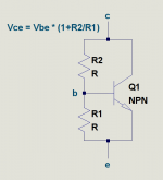
Anyone ever try using a Vbe multiplier to replace an LED? You can dial in any reasonable voltage drop you want from 0.7V upwards by using a trimpot for (R1+R2) in the attached schematic.
I would expect a Vbe multiplier to behave very similarly to an LED otherwise. Both have the same exponential current-voltage characteristic, and if adjusted to the same voltage drop at the same forward current, they will probably behave pretty similarly for small-signal AC changes as well.
The one obvious difference (the Vbe multiplier has a parallel resistance equal to (R1+R2) across the "LED" ) should make very little difference, as R1+R2 will be much greater than the dynamic (differential) resistance of the multiplied diode.
-Gnobuddy
Attachments
Biguns comment above that the LED is effectively a constant voltage source so the tube is running fixed bias prompts another thought. The max Rg1 value for fixed bias is much lower than for Auto (cathode bias resistor) bias. You may need to change the grid leak resistor to a lower value when using LED bias.
I'm still looking for a current controlled voltage source for cathode biasing although that TL431 circuit would seem to be headed that way.
Cheers,
Ian
I'm still looking for a current controlled voltage source for cathode biasing although that TL431 circuit would seem to be headed that way.
Cheers,
Ian
The first electronics I learned about was simple one-transistor circuits. Since transistors parameters had very sloppy tolerances, the only way to get a stable operating point was to make sure the external biasing circuitry provided it, no matter what the transistor itself did (within limits, of course.) So I learned to think about operating point stability as part of the biasing scheme....the LED is effectively a constant voltage source so the tube is running fixed bias...
Valves have far stabler parameters, so we can sometimes get away with bias schemes that produce very little additional stability of their own (such as LED bias.) Nevertheless, there are times when it is useful to think about them in the same way that designers used to think about transistors - i.e., consider what the external biasing scheme is doing to help or hinder the valve in maintaining a stable operating point.
To bias a simple triode valve, we can use any of these: a fairly small external cathode resistor to ground, a much bigger external cathode resistor to a negative voltage rail, a constant current source between cathode and ground, or an LED (approximately a constant voltage source) between cathode and ground.
For stability of the desired bias point, what we are interested in is the derivative dIk/dVk, where Vk and Ik stand for cathode voltage and cathode current as usual.
If this derivative is zero, the cathode current is perfectly stable. If this derivative is infinity, the cathode current is no longer stabilized by whatever we have connected externally to the cathode. Stability is intermediate for intermediate values of the derivative.
Now lets consider each of these possibilities in turn.
1) Cathode resistor: For an old-fashioned pure cathode resistor Rk, the derivative (dIk/dVk) is equal to (1/Rk). The bigger Rk is, the smaller the derivative is, and the stabler the operating point. So the way to get a very stable operating point when biasing with an external cathode resistor is to return the other end of Rk to a negative voltage rail, which lets you use a bigger cathode resistance for the same cathode current and grid bias (Vgk).
Alternatively, you can bias the grid positive by a number of volts, which also lets you use a big cathode resistor. A cathode-follower is a practical example, the bias point is very stable because of the large value of the external cathode resistance Rk.
2) Current source: For an ideal current source between cathode and ground, dIk/dVk is zero. The cathode current is perfectly stabilized, and you can plug in any old triode and still get exactly the same cathode current. Reality is not quite ideal, but very close to it. If you want the stablest of all operating points, use a constant current source to set the cathode current!
3) And finally the voltage source: for an ideal voltage source, dIk/dVk is infinity. This means the tiniest of tiny voltage changes is enough to cause an enormous current change. A pure voltage source at the cathode does nothing whatsoever to stabilize Ik; the cathode current is determined entirely by the triode itself, and that means it is sensitive to variations in valve parameters, ageing, and so on.
Old habits die hard, I learned at an early age to design bias circuits to provide stable operating points, and it is the almost complete lack of external stabilization that has kept me from trying LED bias in my valve projects. That, and concerns about additional (and unpleasant-sounding) THD caused by the nonlinearity of the LED's I/V characteristic.
I'm not saying my concerns are valid - enough people have tried it, measured the results, and shown that LED bias works well in many cases. Well-made valves are stable enough to be usable even with no external help from the biasing scheme. LED-induced THD is low enough not to matter in many circumstances. I should get over my concerns and try it.
But, with all that said, there is no doubt that LED bias (like fixed bias) provides virtually no help to the valve at all, when it comes to maintaining a stable operating point.
-Gnobuddy
Note that in the 1920s it was common practice to solder a teeny 1.4V battery in the grid lead of an input triode. Fixed Bias.
I too felt that fix-bias would be unaccommodating to supply changes. However I plotted it out once and, assuming your B+ rail tracks your wall-outlet voltage, it isn't a real problem. You will be groping in the dark, or replacing all lamps every hour, before a nice-design LED-bias stage gets far from its happy point.
In part because a triode IS always "self bias" due to plate resistanCE against DC plate resistOR. If it pulls more current, Vp falls, it pulls less current. For reasonable values, deviations are significantly reduced.
Attachments
Note that in the 1920s it was common practice to solder a teeny 1.4V battery in the grid lead of an input triode. Fixed Bias.
Just wanted to show how it was done....
Attachments
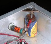
Yikes. That should be taught in Kludging 101 - they didn't even bother to insulate the edges of the metal disk, so if you mis-position it, you short out the cell!
Thanks for the picture! 🙂
-Gnobuddy
Thanks for the picture! 🙂
-Gnobuddy
That's a bodge.
No, they *made* grid batteries, small as watch batteries, leaded or in minimal holders. "Bias Cells". Went right in series with the grid, not shunt as in the kludge you show. Because current was "zero", they lasted until they dried-up. 50 years later, restorers drill holes to inject a part-drop of damp, they come back to life.
http://www.charlestonarea.com/Dickerson/BiasCell.jpg
http://www.antiquewireless.org/uploads/1/6/1/2/16129770/09-the_mallory_bias_cell.pdf
A little acorn-shaped bias cell? Very cool. Thank you for that bit of history!No, they *made* grid batteries, small as watch batteries, leaded or in minimal holders. "Bias Cells".
-Gnobuddy
Would using a separate low voltage power supply and lower resistance resistor to feed the 6ma thru the LED work just as well as pulling the 6ma via the bigger resistor off the B+ supply? Assume a regulated say 12VDC supply feeding a 1666 ohm resistor to the say a red LED. Idea is to avoid heavy loads on the B+ supply.
Hi, I'm reading this interesting discussion (as well as many others on led bias) as I have an ear834 phono to which I wanted to implement the led bias in the first two stages.
At the moment the Vk of the first stage is 0,671v / 0,654v and the second 1,141v / 1,134v.
I have different types of LEDs (including IR (1.2v), Red 2mA, etc...) but I think I understand that putting them directly is not good as there is little current.
Can I then, without loading the B +, take the current from the stabilized 12.6vdc (Lt1083) of the filaments and give some current to the LEDs?
But which led? Which VF?
Current B+ are:
on V1 285v (330K),
on V2 294v (330K),
on V3 (CF) 299v (6n1p, Grid -5, Rk 23.5k, and current 5.05 mA.
Thanks for any advice and help to optimize 🙂

Last edited:
I currently have a 12Ж1Л Pentode running at about 1mA with a CCS and LED bias. Cathode LED and Anode LEDs share the same resistor. See attachement. works well, of course with feedback due to gigantic amplification.
This is exactly what I do with 1Zh29b/24b and it works fantastically well to linearise them (using ztx558 and bc557/560, at about 1mA)
makes me wish i never published my fixed bias schematics on ValveJunior.com...now I see everybody else doing it ; and other(s) taking all the credit for it ......
This is exactly what I do with 1Zh29b/24b and it works fantastically well to linearise them (using ztx558 and bc557/560, at about 1mA)
which led? : P curious me! scheme? : P
- Home
- Amplifiers
- Tubes / Valves
- Cheap Red LED bias on ecc83/12ax7