My electronics experience is mostly in years of Synth DIY. I felt confident about building a LM3886 amp to drive my monitor speakers, but after reading several threads about chipamp builds I believe there may be some black magic and voodoo involved that I do not totally understand.
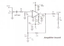
I was originally going to build my amp on vector board using one of the many designs available, but while ordering the chips I noticed I could buy a set of PCBS for it for an additional $4. Why not?
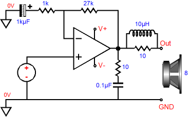
There's a couple of things on the schematic that came with the boards that I'm not quite sure about. There's a 22uF 500v cap on the input right after the pot. Seems a little excessive. Is there some sort of magic that comes from hugely over rated DC blocking capacitors (I'm assuming this is the purpose of this cap)? How should I gauge a substitutions?
There is also a 1ohm resistor shown between the output and the speaker. Seems weird to me. Not sure what it's doing there. I've seen resistors to ground off of the output on other designs, but not a resistor in the signal path. I assume this would need to be a 3 - 5 watt resistor as well?
The power supply board seems to be the CarlosFM design that you've all answered plenty of questions about, so all my questions about that I've found in other threads.
I can scan the schematic if necessary. Thanks for any help. I hate asking questions, so I promise I won't make it a habit.
I was originally going to build my amp on vector board using one of the many designs available, but while ordering the chips I noticed I could buy a set of PCBS for it for an additional $4. Why not?
There's a couple of things on the schematic that came with the boards that I'm not quite sure about. There's a 22uF 500v cap on the input right after the pot. Seems a little excessive. Is there some sort of magic that comes from hugely over rated DC blocking capacitors (I'm assuming this is the purpose of this cap)? How should I gauge a substitutions?
There is also a 1ohm resistor shown between the output and the speaker. Seems weird to me. Not sure what it's doing there. I've seen resistors to ground off of the output on other designs, but not a resistor in the signal path. I assume this would need to be a 3 - 5 watt resistor as well?
The power supply board seems to be the CarlosFM design that you've all answered plenty of questions about, so all my questions about that I've found in other threads.
I can scan the schematic if necessary. Thanks for any help. I hate asking questions, so I promise I won't make it a habit.
There's a 22uF 500v cap on the input right after the pot.
No voodoo, It is probable a film cap and they are often only available in such a high voltage ratings with this capacitance. Personally, I dislike huge components in the signal-flow. It only add's more inductance.
With kind regards,
Bas
Thanks for the response.
Ah, so I could do without it? I've seen input caps everywhere from .22uf to 22uF, what's the difference? I'm actually debating that, but since I'm using this to power monitor speakers for a modular synth DC blocking might be a good idea.
So then what do you think this 1ohm resistor is for?
Ah, so I could do without it? I've seen input caps everywhere from .22uf to 22uF, what's the difference? I'm actually debating that, but since I'm using this to power monitor speakers for a modular synth DC blocking might be a good idea.
So then what do you think this 1ohm resistor is for?
The input capacitor forms a highpass filter with the input resistor. The higher the value of the capacitor, the lower the frequency cutoff, and the more deep bass you get. With a standard 10k input resistor, the capacitor stops being important past 2.2uF (10k/2.2uF has roughly a -3dB point of 7Hz).
Unnecessarily large input cap can cause audible transients (popping) at turn on. As for the 1ohm resistor, i don't think that was supposed to be there. Or if it was... it should probably be 0.1ohm if it's in series with the speaker.
Unnecessarily large input cap can cause audible transients (popping) at turn on. As for the 1ohm resistor, i don't think that was supposed to be there. Or if it was... it should probably be 0.1ohm if it's in series with the speaker.
Are you sure that resistor isn't supposed to be more like 10R with a wire wrapped around it to form an inductor in parallel?
Like in this schematic.....
Like in this schematic.....
The 1 ohm resistor is there for if you want to parralel the boards. If you are not going to and only use the boards in "single" mode. you can easily rather populate a wire link in the place of the 1ohm oputput resistor.
The 1 ohm resistor is there for if you want to parralel the boards.
Explainable, but 1 ohm still seems a bit excessive to me. Or is the LM3886 different than transistor amps?
ok, ok, I'm building. I'm skipping the 1ohm resistor and subbing the 22uF with a smaller value. I can always change it later if I don't like it.
Thanks for the advice everyone!
Thanks for the advice everyone!
Hi
Are they blue boards from the far east ?
The small set of instructions say ' Carlos Fm ' on the power supply stage ?
If this is correct 2.2 uf on the input cap is fine and the 1 ohm resistor before the output is also fine.
I too wrangled with the 22 uf 500 v nonsense.
It's a typo on the instructions.
Let me know when you can - I think I built this item already as it was cheap and easy to understand, plus it worked first time and sounded good too.
Andrew
Are they blue boards from the far east ?
The small set of instructions say ' Carlos Fm ' on the power supply stage ?
Yup, that's the boards! I'm building them right now. I guess I will put that 1ohm resistor in after all.
Hi
You didn't make a mistake buying them at all.
I've built all of mine using them and they are fantastic actually.
I now have mono blocs with two traffos and two sets of smoothing and
rectification boards.
Doing this was a big step up again.
I used Dale Vishay resistors, Muze KZ caps and Ampohm input caps.
Two 300 VA 25 v traffo's and silver wire too.
Keep going -you'll be glad you did
Regards
Andrew
Hi,
keep the 1r0 in the output feed.
Add a 1uH air core inductor in parallel to the 1r0. This converts the output from a Zobel load to a Thiele Network for amplifier output.
The Thiele Network helps avoid instabilities in the amplifier better than a Zobel alone.
The 22uF 500V and 10k for the input filter is a bad recommendation.
Try using between 470nF and 4u7F plastic film cap at the input as your DC blocking capacitor.
I like the bass sound that comes from using 1uF and 91k giving an F(-3dB)=1.7Hz. This is roughly equivalent to the specification of -1dB @4Hz that is fairly common in good retail offerings.
You can mimic the same high pass rolloff with any RC combination that has a 91ms RC time constant.
However I believe this works only when this input filter determines the bass response of the amplifier. This demands that the NFB cap be sized to match the input cap.
NFB cap >= sqrt(2) * Cin * Rin / Rfb.
Many use the NFB cap to roll off the bass rather than at the input and I think this gives poor bass sound. It's fairly easy to add parallel caps in these two locations if you start with both being too small and find what combinations suits you, your speakers and your room.
Using the values in post6
NFB cap >= 1.4 * 22uF * 22k+1k / 680r >=1050uF ( a silly number for this amplifier.) Any smaller than 560uF and the NFB cap becomes the passband filter (= bad in my opinion).
Change Cin to 2u2F and the NFB cap becomes >=105uF. Use 120uF or 150uF or 220uF (not 22uF).
Last edited:
Ok, I built it. I think it sounds surprisingly nice, but I'm no audiophile. It's a bit underpowered right now. The transformer I picked up was labeled as 24-0-24, but It seems to only be putting out 17-0-17.
The thing that stands out the most to me is the lack of hiss and noise even when there is no signal. Maybe I'm in awe of something ridiculous, but I'm used to having a lot of it with my old combo of crappy receiver, or PA amp + computer (m-audio Delta-44) sound card.
The thing that stands out the most to me is the lack of hiss and noise even when there is no signal. Maybe I'm in awe of something ridiculous, but I'm used to having a lot of it with my old combo of crappy receiver, or PA amp + computer (m-audio Delta-44) sound card.
Hi,
yes, a good power amp should have a maximum output to noise ratio approaching 120dB.
A poor amp will be less than 100dB. Even that will be relatively low in noise at the speaker cone. An excellent power amp will exceed 120dB S/N ratio
To achieve these results the good amplifier must be wired up correctly.
Expect a chipamp to read <=0.2mVac across the speaker terminals. Some will read <=0.05mVac.
- Status
- Not open for further replies.
- Home
- Amplifiers
- Chip Amps
- Cheap LM3886 PCB I probably shouldn't have bought.