Hi Folks!
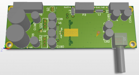
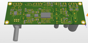
By request from my friend I made (of may be 90% trough) layout of simple standalone two layer PCB for amplifier mentioned earlier in parallel universe.
Schematic of this version can be found here. This guy also has on the board preamplifier with volume control and simple output DC protection.
If anyone will be interested in construction of this thing, I can provide gerber files and BOM.
And an addition few 3D pics of the PCB (not the latest version one though).
Attachments
Last edited:
Very interesting design, I'm sure it's an awesome performer. It looks like you are using a form of modified integrator compensation around the TPA6120?
Also curious as to how you arrived your zobel network values?
Also curious as to how you arrived your zobel network values?
clamping is helpful in composite amps - I show a scheme for diode feedback clamping the input op amp that should give faster recovery, input op amps would draw less current in clipping:
http://www.diyaudio.com/forums/soli...ain-composite-op-amp-circuits.html#post512806
filtering the input op amp supply is OK, but you can afford to add sub regulation to a lower V - whatever the input op amp is happy with
could be Zener shunt reg - could take up less room than big electrolytic C, works down to DC
while a project schematic may benefit from the mediafire service - it was a major pain for me
for discussion please just use forum attachment or img so I can see something without changing browsers, downloading
HI Jcx
I actually was thinking about this sort of clamp (not exactly the same, but essentially the same structure) and actually prototyped it but decided to give it a miss for couple of reasons:
1. Clipping and recovery for this device will not be a part of normal operation. It has a gain of 1 and used with DAC which has 2Vrms output. So clipping is excluded, except start up and power down, where more sophisticated clumping circuit didn't make too much difference.
2. This clump has some parasitic capacitance from output of opamp to its input, and this capacitance is non-liner. I observed some difference in distortion level while clamp was connected. The difference was not particularly large, and when amplifier is heavily loaded it is below practical level, but still, when you know that it is somewhere over there...
I could try to use PIN diodes, which typically have 5-10 times lower capacitance than bav99, but I did,'t get to this point.
Post regulation was crossing my mind as well, but result was satisfying with simple RC - why to bother.
Hi Chris
Zobel values where some sort of attempt to kill two birds and at the same time to use existing on the board values.
I was chasing two things 1. Disconnect amplifier on a high frequency from potentially capacitive load and give it more of less stable active loading. 2. Sort of "terminate cable", or in other words introduce some losses on high freq.
I would prefer to have some what larger inductor value, but it's size was getting impractical.
- Status
- Not open for further replies.
- Home
- Amplifiers
- Headphone Systems
- Cheap but linear headamp