Spare PCB
I just got the two PCBs for this DAC in the mail from OLIMEX. Since I have a spare one, if you need it, send an email to trifonov"AT"interchange.ubc.ca
I'll send it to you for a very low price (make an offer) + shipping.
If you are in Vancouver, BC I'll give it to you for free if you show me your DIY projects -- I've not met any DIYers in Vancouver yet, and I'd love to check out other projects.
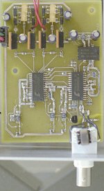
The PCB has the solder masks and silk screen (rather than the parts shape layer I used the part numbers so I know where goes what, i.e. IRF610, 7uF, etc.)
I'll first build the DAC to make sure the boards are good (they look fine on visual inspection).
BTW, is it OK to do the soldering of the SMD parts with a 45 W soldering iron, or is that too much? Can I just put a resistor in series with the iron (perhaps a light bulb), and how do I know how much? Thanks.
I just got the two PCBs for this DAC in the mail from OLIMEX. Since I have a spare one, if you need it, send an email to trifonov"AT"interchange.ubc.ca
I'll send it to you for a very low price (make an offer) + shipping.
If you are in Vancouver, BC I'll give it to you for free if you show me your DIY projects -- I've not met any DIYers in Vancouver yet, and I'd love to check out other projects.
The PCB has the solder masks and silk screen (rather than the parts shape layer I used the part numbers so I know where goes what, i.e. IRF610, 7uF, etc.)
I'll first build the DAC to make sure the boards are good (they look fine on visual inspection).
BTW, is it OK to do the soldering of the SMD parts with a 45 W soldering iron, or is that too much? Can I just put a resistor in series with the iron (perhaps a light bulb), and how do I know how much? Thanks.
Re: Spare PCB
I have a WSP80 Weller 80 watts! The key is the temperature. If you iron has temperature regulation it's OK but 45 W without _can_ be too much. Normal temperature is 250-300 deg C. Unregulated iron can have a 450 deg tip!
Resistors and semiconductors can take high temperature but caps are more sensitive, especially those of plastic.
Prune said:BTW, is it OK to do the soldering of the SMD parts with a 45 W soldering iron, or is that too much? Can I just put a resistor in series with the iron (perhaps a light bulb), and how do I know how much? Thanks.
I have a WSP80 Weller 80 watts! The key is the temperature. If you iron has temperature regulation it's OK but 45 W without _can_ be too much. Normal temperature is 250-300 deg C. Unregulated iron can have a 450 deg tip!
Resistors and semiconductors can take high temperature but caps are more sensitive, especially those of plastic.
SMD soldering
You can find informations on SMD soldering if you search, or visit some pages.
For example:
Soldering page
On same page:
SMD soldering guide
But on many other pages many informations available also.
You can find informations on SMD soldering if you search, or visit some pages.
For example:
Soldering page
On same page:
SMD soldering guide
But on many other pages many informations available also.
Well I soldered the thing together yesterday, but I'm having some problems. Only one of the 5 V regulators is actually outputting 5 V; the other two have voltage that varies over time around a couple of volts; the adjustable regulator is only giving out about a volt (these voltages measured in-circuit with everything in place).
I thought the power supply might be too weak (I'm using 1.5 A regulators in the power supply), but the input voltage still reads 10 V and doesn't drop.
I checked all connections and they seem fine. I've no idea how to begin debugging this...sigh
I thought the power supply might be too weak (I'm using 1.5 A regulators in the power supply), but the input voltage still reads 10 V and doesn't drop.
I checked all connections and they seem fine. I've no idea how to begin debugging this...sigh
With a magnifying glass, probably.


Check for solder bridges and make sure that you got pin 1 oriented properly on the regulators. Take your time, and don't be afraid to take one apart altogether.
If you have a good camera maybe you can take a photo of one of the regulators and post it here.
Check for solder bridges and make sure that you got pin 1 oriented properly on the regulators. Take your time, and don't be afraid to take one apart altogether.
If you have a good camera maybe you can take a photo of one of the regulators and post it here.
> take one apart altogether
I was talking about the LT1962-5 +5V and LT1962 adjustable regulators in the schematic. They are ICs, I can't take them apart.
I'm worried about the soldering heat effect on the ICs. I'm using an unregulated 35 W iron, since I have nothing else. On the one hand, I know at least the resistors and the MOSFETs don't have a problem (I tested heating some for 30 s and it didn't burn them out), but I'm not sure if I might have wrecked the DAC and/or sample rate converter, though I don't know how to check for that.
BTW, since I already had ZTX869 I used them rather than ZTX450; that shouldn't be a problem, right? I tried running an external signal through the IRF610 analog part and at least that seems to work fine.
Where do I ground the ground plane at the input connector?
I'll borrow a camera tomorrow and post a picture.
My only source of a digital signal is the SBLive SPDIF out, which I think is 5 V, not coax, so I don't know if it's compatible; I read on the net that people have hooked it up to coax digital-in on receivers and worked fine. The plug on the card is a stereo mini jack, which seems strange to me since it has 3 conductors and coax has 2...
What the?! For the stuff connected to pin 8 (filter) of the CS8420, you have swapped the 0.47uF capacitor with the 1.8K resistor as compared to the schematic...what's going on here?
Also, can you post your power supply design? And if I use the ZTX869, do I need to change the values of anything else?
Thanks, your help is greatly appreciated!
Well, yes, but I think the filter circuit is equivalent.
The ZTX869 and 450 are interchangeable for this application aside from their cost. And you said the buffer stage works correctly, right? Is any part of the circuit drawing excessive current?
The ZTX869 and 450 are interchangeable for this application aside from their cost. And you said the buffer stage works correctly, right? Is any part of the circuit drawing excessive current?
> And you said the buffer stage works correctly, right?
I'm guessing that is the case, since when I feed it a signal from my CDP, I can hear it from the output (connected to my headphone amp). Also, if I use the voltmeter at the output points (before the decoupling capacitors), they have 3 to 3.5 V DC.
> Is any part of the circuit drawing excessive current?
Yes!, the one connected to VREF and VA of the CS43122. In fact, when I power the other regulators individually, they do give out 5 V. This is really weird: usually it gives half or one volt from the adjustable regulator, rarely it shows 5.5 V (it changes when I remove and reapply power); I cut the trace to VA so it was only feeding VREF -- same thing. I tried unsoldering pin 1 of the adjustable regulator, and then it gives out the input 10 V. I also checked all the capacitors on that line, and they are fine.
 Anyone?
My main thought was one of those big surface-mount electrolytic capacitors is probably shorting something out. They aren't specified, and they certainly look cramped.
It's not the capacitors: I checked by taking them off.
It's the VA pin. If I disconnect it and apply power to the CS43122 section I get 5.5 V from the adjustable regulator; if I connect VA, the voltage drops to around 3 V (input power stays at 10 V). Also weird that if the VA is not connected to the regulator output, but the other pins are (VREF and MUTE), VA is at 4 V all by itself, disconnected.
In these tests the clock is not running since I broke that regulator and haven't gotten a replacement yet. But that shouldn't matter for these results, no?
Do you think I should buy another CS43122 and try to replace this one?
Thanks.

It pretty much has to be a short circuit. I don't think anybody will want your money, but I hope someone else will have a look at your photo.
> I don't think anybody will want your money
Probably, but I've nothing to lose by asking 🙂
> It pretty much has to be a short circuit
So you don't think I could have damaged the chip? I'm afraid I used an iron without temperature control.
I unsoldered the CS43122 VA pin and tried to feed a 5.5 V source directly to it, and it draws a quarter of an amp!
I tested with an ohmmeter for a short between VA and the rest of the pins. The only thing that I found was that between VA and one of the outputs, AOUTR-, there is only about 17 K resistance, whereas the resistance between VA and the other outputs is in the megaohms.
jwb, do you think you could tell me what the resistances between VA and the four outputs are in your DAC so I can compare?
After using this for a very long time, I finally have time to make a box for it. However I want to add a TOSLINK input, say with a receiver such as TORX176.
I'm not sure how to properly connect it along with the existing transformer-based coaxial input. Looking at the CS8420 datasheet, there's a 0.01uF between the receiver and RXP. So can I just hook this up even though the transformer is already connected to RXP?
I'm not sure how to properly connect it along with the existing transformer-based coaxial input. Looking at the CS8420 datasheet, there's a 0.01uF between the receiver and RXP. So can I just hook this up even though the transformer is already connected to RXP?
- Status
- Not open for further replies.
- Home
- Source & Line
- Digital Source
- Cheap 24/96 DAC, Revision B.