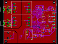
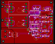
It´s suppose to, the CS4390 can, here´s a link to a dac that uses tranformer coupling anyway it does convert the balanced out, so I get double the signal level:
http://digilander.libero.it/paeng/a_24_bit_dac_full_article.htm
here´s another pic showing only components mounted on top side,
/ Micke
http://digilander.libero.it/paeng/a_24_bit_dac_full_article.htm
here´s another pic showing only components mounted on top side,
/ Micke
Attachments
JWB,
Which is your impresion of the sond provided by this circuit?
How much will you be paying for the board?
Which is your impresion of the sond provided by this circuit?
How much will you be paying for the board?
I haven't built the revision B board. You'd have to ask someone who has. On the revision A, I paid $30/board. The sound is quite a bit better than the NAD CD player that feeds it. The sound is simply much less harsh. I notice it the most when I really want to turn it up. On the NAD, if I turn the music up very loud, it is difficult to enjoy. But with this DAC I can enjoy it even at very high levels.
The problems with this DAC are:
1) The grounding on the first revision was suboptimal, leading to noise.
2) The CS8420 really should be used in software mode, because hardware mode has a few bugs that can cause it to lock-up.
3) The power regulation could be improved.
With the version posted by hifi above, the grounding problems should be improved. Micke, how big is that board? It looks huge!
jwb said:The problems with this DAC are:
1) The grounding on the first revision was suboptimal, leading to noise.
I mentioned somewhere else that groundplanes and separation of digital and analog ground is very important. You see, this IS very important if you want the lowest noise possible. All manufactures recommends very narrow bridge between the analog and digital groundplanes and it's located under the DAC chip.
Hello,
>> JWB The board is about the same size as yours 98x83mm I just moved some stuff around a bit.
>>Peranders, is this the way you would recomend the groundplanes? but then I would not use the isolation properties of the transformers fully...
And this board have the oscillator mounted directly above the CS8420. and also balanced outputs.
/micke
Attachments
Tut tut peranders; no gloating please. Anyway I have no evidence that the split ground plane improves the situation. My PCM1704 DAC has a single ground plane and is very quiet.
-jwb
-jwb
Separation of Ground Planes
JWB,
Tut, tut, gloating???
My experience is better sound with analog & digital groundplanes separated by a ferrite bead as suggested in some AD datasheet. I have even gone further and replaced the ferrite bead by a ferrite cored 2.2mH inductor at the powersupply. The latter is contrary to AD's suggestion to place the bead at the DAC. The bead at the DAC produced a lot of noise in my loudspeakers.
/Maybe my last post before getting banned.
Hurrah

Re: Separation of Ground Planes
Why???
 😕
😕
What's going on around here?
mlloyd1
Why???

 😕
😕 What's going on around here?
mlloyd1
Elso Kwak said:..../Maybe my last post before getting banned.
Banned???
Hi Michael,
Please see:
http://www.diyaudio.com/forums/showthread.php?postid=155812#post155812

Hi Michael,
Please see:
http://www.diyaudio.com/forums/showthread.php?postid=155812#post155812

Gloat, I had to look in a dictionary, new word for me...jwb said:Tut tut peranders; no gloating please. Anyway I have no evidence that the split ground plane improves the situation. My PCM1704 DAC has a single ground plane and is very quiet.
I don't mean gloating. I only wanted to say it really hard to get it right with a high performance DAC. One thing is hearing (noise) an another is to make it quite in RFI/EMI which in Europe is a serious matter.
Power supply
I am basing the power supply on the design here:
http://headwize2.powerpill.org/projects/showproj.php?file=pawliw1_prj.htm
(Figure 2 on that page), scaling components appropriately.
What would be the best way to split the output from this for the digital and analog sections?
I am basing the power supply on the design here:
http://headwize2.powerpill.org/projects/showproj.php?file=pawliw1_prj.htm
(Figure 2 on that page), scaling components appropriately.
What would be the best way to split the output from this for the digital and analog sections?
How do I change the drill size for the pads? Some of the current holes in the pad layer are too small for my manufacturer. I tried to change them in Eagle, but it won't let me select anything on the pads layer. Any help would be appreciated, as I'm pretty new to Eagle. Thanks in advance.
You should check the drill sizes in your manufacturing files before you send them off. I almost always need to fudge them a bit to make them exactly the sizes provided by PCB Express. I simply edit the drill file by hand.
Wiggling the EMI probe
I built the EMI probe described in Linear application note 70, and used it with this DAC. I hooked it up to a Tek 2465A scope, triggering on some high-frequency noise on the analog output of the DAC. What I found was pretty interesting! The clock chip that I used in this design is a pretty heavy radiator. The emissions near the clock output pin are enough to induce a ~30mVp-p 49MHz signal in this passive, unamplified probe. Perhaps this could be reduced with a proper source termination of the clock line.
Other strong radiators were the short traces between the decoupling capacitors and the digital power pins of the ASRC and DAC chips. I'm not sure how to reduce these. The capacitors are already nearly atop the pins.
Anyway, it is a fun experiment and it is clear that the emissions in this unit could be reduced!
Oh, incidentally related to the "high-speed diodes" thread, I did not measure any emissions near the IRF HEXFRED soft/fast recovery diodes used in the power supply. I also could not measure any recovery-induced ringing on the transformer secondary (using a regular probe).
jwb,
Sorry to sidetrack, but I'm interested in the probe you mentioned. I just read the appnote, and it looks like a very useful little tool indeed! So, I think I'll build one... maybe even later this afternoon. 🙂 What dimensions did you use (the most vague dimension in the appnote is the slot length), and any tips on construction?
Sorry to sidetrack, but I'm interested in the probe you mentioned. I just read the appnote, and it looks like a very useful little tool indeed! So, I think I'll build one... maybe even later this afternoon. 🙂 What dimensions did you use (the most vague dimension in the appnote is the slot length), and any tips on construction?
hifi,
I didn't have any #34 wire, so I used ten turns of #30 wire with a coil diameter of .060. The brass tube is .125 od, .096 id; just big enough to fit the coil and the resistor. I cut the slot long enough to expose the entire coil, probably about .250. The whole probe, including the connector, is about 2.4in long.
Some trickery is needed to seat the pin in the BNC connector without shorting it against the brass tube. I sort of crimped the tube around the resistor so I could apply force without destroying the pickup coil. You could probably use a little slice of dielectric as a shim, too.
Well, I now have a completed sniffer probe. Specs are basically identical to yours, and I managed to get away without any dielectric shims, although I did use a little plumber's teflon tape on the leads of the resistor. We'll see how (or if 🙄 ) it works in the next day or two.
Thanks for pointing me to the article jwb, this should be a useful little tool. 🙂
Thanks for pointing me to the article jwb, this should be a useful little tool. 🙂
- Status
- Not open for further replies.
- Home
- Source & Line
- Digital Source
- Cheap 24/96 DAC, Revision B.

