The Cheap150 has C3, but it's directly on the input. Adding the R8 and moving C3 would be a good mod.Why does the Citation 12 have all those extra parts?
R8 and C3 keep RF out of the amplifier.
R9 and R6 are the same value to reduce DC off-set.
C6 improves stability at high frequency.
C8 and R19 improve stability at high frequency. Today 11:10 AM
R9 and R6 are the same for the Cheap150. They're 22k-Ohm.
The Cheap150 has C6.
C8 and R19 would be a good mod as would L1 and R18.
Even without the extra stability mods, I'm not seeing any problems with HF ring. I've got the Rogue PA off the bench and tested it with a set of speakers. Sounds at least as good as it did when I sold it. Ran some MP3s through it for a few hours at loud volume and all is well.
Being from the live music side, I think this amp really needs some overload protection. If it were in a powered speaker or a sub, it wouldn't be such a problem. I don't have control over the garbage cables or number of speakers the user will plug into it so sometimes it's a dead short. This amp will last about a half a second with a dead short. I know that for a fact.
Hey BurnedFingers, look at this!
An externally hosted image should be here but it was not working when we last tested it.
Got it from the Cheap150's emitter resistors and immediately thought of you! 😱
Not to mention that i've seen schematics from reputable designers here on the forum that dont use the zobel link and output inductor either.
Yes, you'll see and read any number of things here, but are they all true? Are they all accurate? Is the advice you are getting good?
If you feel the output inductor has a bad effect on the 'sonics', do a comparison. It isn't much work to make up and tack onto the output, then you can listen and hear for yourself (rather than trust someone else's opinion) as to whether it has any impact on the sound.
BTW, a Zobel will get hot (the resistor) when an amp is oscillating - a cheap detector.
I dident mean sonics, i meant harm to the amp.
What is this inductor for anyways ? I've seen things like phase compansation and that kinda stuff. I guess it also takes the edge off oscillations and possibly help saving a tweeter if the amp goes into oscillation.
What is this inductor for anyways ? I've seen things like phase compansation and that kinda stuff. I guess it also takes the edge off oscillations and possibly help saving a tweeter if the amp goes into oscillation.
I dident mean sonics, i meant harm to the amp.
What is this inductor for anyways ?
It protects the amp from capacitive loads. The Zobel protects the amp from inductive loads. They protect the amp, not harm it.
Got it from the Cheap150's emitter resistors and immediately thought of you! 😱
?? The emitter resistor on one of the outputs? That doesn't sound good.
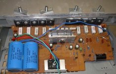
Let me tell ya, Man of Action, it was no fun at all! I was testing the amp without heatsinks just to see if it worked. To my surprise it did! So I got carried away taking some pictures and, all of a sudden... it stopped working. So I checked the output emitter resistors to see if they were getting hot, and boy were they! Needless to say, both the output darlingtons were fried.
Next, after fixing it, I wanted to see how the amp behaved with a dead short. Well, it didn't. It fried the TIP147 (minus rail PNP darlington) along with its emitter resistor.
So I've gone through 3 output transistors, one emitter resistor and a light-gauge jumper wire while testing this amp. Fortunately the TIP142 & 147 devices are super cheap at element-14.com (the tinkerer's side of the house at Newark). Get this, the STMicro 142's are $1.14ea. and the 147's are $1.36ea. And those are the hefty 125W transistors in the TO-247 package, not the 80W TO-220 devices!
Last edited:
Thought they were getting that hot during normal use - that would be not-so-good.
On one of my first ever builds, looong ago (ok, 6 years, but that's a looong time in iternet years...🙂 ) I shorted the output with nearly full input. The breaker on the panel tripped, the 'traces' (point to point copper 24awg wire) evaporated, most of the emitter resistor opened and I nearly had a coranary...but the outputs survived. MJL21193/94 - tough enough to withstand that, I believe that would be fine (assuming enough devices for SOA) with just a fuse on the output.
On one of my first ever builds, looong ago (ok, 6 years, but that's a looong time in iternet years...🙂 ) I shorted the output with nearly full input. The breaker on the panel tripped, the 'traces' (point to point copper 24awg wire) evaporated, most of the emitter resistor opened and I nearly had a coranary...but the outputs survived. MJL21193/94 - tough enough to withstand that, I believe that would be fine (assuming enough devices for SOA) with just a fuse on the output.
Sounds exciting. Those were the good olde days... 🙂
Yeah those MJL21193/94 are beasts. Nothing like a TO-3 package. So I just got some MJ11032/33 power darlingtons, 120V 300W 50A. They're kind of the high gain version of the MJL21193/94. My plan is to build the SOC150 (Son of Cheap150) with those. I'll 2x the ouptuts (parallel) and add some of the enhancement suggested here. Most of the enhancements will be "build-time optional," of course. 🙄
Yeah those MJL21193/94 are beasts. Nothing like a TO-3 package. So I just got some MJ11032/33 power darlingtons, 120V 300W 50A. They're kind of the high gain version of the MJL21193/94. My plan is to build the SOC150 (Son of Cheap150) with those. I'll 2x the ouptuts (parallel) and add some of the enhancement suggested here. Most of the enhancements will be "build-time optional," of course. 🙄
Oh, not as beastly as I thought. I was thinking MJ21195/96. The TO-3 darlingtons are even heftier and under seven bucks a pop... er I mean seven bucks a crack... er I mean seven bucks each. (Don't want to jinx the SOC150.)
That's quite the amp you've got there -- 5 per rail? With a 250 Vce, that design should easily run your stage lights. 🙂
That's quite the amp you've got there -- 5 per rail? With a 250 Vce, that design should easily run your stage lights. 🙂
Wouldent a properly designed VI limiter make an amp almost indestructible in terms of shorting ?
5 per rail? With a 250 Vce, that design should easily run your stage lights. 🙂
This has taken its place:
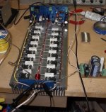
I've never tried darlingtons in an amp before. Generally, the preferred way is to use separate drivers. I don't know if paralleling darlingtons (to increase SOA) introduces stability issues. I may get some to play with.
Wow, 8 per rail! That's quite an amp. Instead of watts, do you measure your amps in feet or (I see you're Canadian) meters, eh? (Sorry, couldn't resist.)
Darlingtons are good and make the amp simple, but I haven't found any PNPs with high voltage plus high power ratings. So there goes the cheap full complementary design. The highest voltage rating for a complementrary pair I've found is 120. So I think that limits you to around 60V rails and the max power out into a 4-Ohm load is around 300W.
Seeing your prior creations, I'm not sure that would be enough for you.
That's a good find. Pd is a little light, just 25W better than the TIP142/147, but looks like a very workable device. At $5 each, you could certainly string a few meters together to dim the lights in the neighborhood. 🙂
I'll consider this for the SOC150 design. This could make the working range of rail voltage from about 12 to almost 250. What's really nice is that there's a range of identical devices rated 150, 200 & 250 volts, so you could pick the parts for your rails.
In the US, you can get 2400W out of the typical wall plug, so 150V rails is about all you'd need.
Thanks
(Couldn't find them because E14/Newark have their data wrong. hfe shown as 15 & no mention of darlington.)
Last edited:
Properly designed VI limiter?
Just wondering, exactly what is the properly designed VI limiter?
Wouldent a properly designed VI limiter make an amp almost indestructible in terms of shorting ?
Just wondering, exactly what is the properly designed VI limiter?
Read Workhorse recent reply to me why the gate protection Zener does not work as a short protection.
There is so much I still have to learn !
There is so much I still have to learn !
add to that that the same diodes will also not protect from a too reactive load .....
( many or too many times amplifiers presented in the forum with plenty of power and inovative audio circuits are not designed to be idiot proof or have inovative protection methods for a change )
( many or too many times amplifiers presented in the forum with plenty of power and inovative audio circuits are not designed to be idiot proof or have inovative protection methods for a change )
Simulations for the Cheap150
I've been off learning how to simulate and thought the Cheap150 would be a good circuit to start with. I used LTspice and the learning curve wasn't too bad thanks to the help I got from the diyaudio Software Tools Forum.
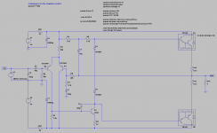
So I used the Cheap150 circuit as originally posted by Mr. Fisher. Here is what it looks like in the simulator:
Here is the simulator output showing the frequency response at 33W and distortion at 6, 33 and 100 Watts. The frequency response didn't change much at different power levels so only one curve is shown:
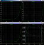
The distortion in the graphs is shown in %THD, and it does not look so good in the simulator -- especially at the higher frequencies. Much of this could be caused by using only two diodes in the bias circuit. This makes the amp operate close to class B.
So I tried a couple simple mods to get the distortion down and yet keep the design very simple. I added a third bias diode to make the amp operate in class AB, and changed a couple emitter resistors for Q2 & Q3. I also added a proper low-pass filter at the input. I don't like using only a 100pF cap across the input as a filter because the corner frequency is set by the impedance of the source signal you plug in. Usually, that's a low impedance making the corner frequency very high, and the filter nearly ineffective. Here's the modified Cheap150:
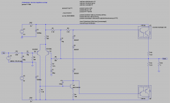
The frequency response stayed pretty much the same, which was good to begin with. The distortion was significantly reduced, especially at high output levels. Here are the graphs:
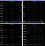
Keep in mind these are only simulations as I don't have the equipment to make actual measurements. I am working on another small mod that promises to reduce the distortion quite a bit and only adds a transistor, a pot and a resistor. I'll post it when I have it.
The result might not be audiophile quality, but it will be cheap -- the operative word here. I'm hoping to make it better and still keep it cheap.
I've been off learning how to simulate and thought the Cheap150 would be a good circuit to start with. I used LTspice and the learning curve wasn't too bad thanks to the help I got from the diyaudio Software Tools Forum.
So I used the Cheap150 circuit as originally posted by Mr. Fisher. Here is what it looks like in the simulator:

Here is the simulator output showing the frequency response at 33W and distortion at 6, 33 and 100 Watts. The frequency response didn't change much at different power levels so only one curve is shown:

The distortion in the graphs is shown in %THD, and it does not look so good in the simulator -- especially at the higher frequencies. Much of this could be caused by using only two diodes in the bias circuit. This makes the amp operate close to class B.
So I tried a couple simple mods to get the distortion down and yet keep the design very simple. I added a third bias diode to make the amp operate in class AB, and changed a couple emitter resistors for Q2 & Q3. I also added a proper low-pass filter at the input. I don't like using only a 100pF cap across the input as a filter because the corner frequency is set by the impedance of the source signal you plug in. Usually, that's a low impedance making the corner frequency very high, and the filter nearly ineffective. Here's the modified Cheap150:

The frequency response stayed pretty much the same, which was good to begin with. The distortion was significantly reduced, especially at high output levels. Here are the graphs:

Keep in mind these are only simulations as I don't have the equipment to make actual measurements. I am working on another small mod that promises to reduce the distortion quite a bit and only adds a transistor, a pot and a resistor. I'll post it when I have it.
The result might not be audiophile quality, but it will be cheap -- the operative word here. I'm hoping to make it better and still keep it cheap.
- Status
- Not open for further replies.
- Home
- Amplifiers
- Solid State
- Cheap 100 to 150 Watt Amp
