As this thread says, this "amplifier" is a non starter!
As I recommended above, build Sixtek's "ST151" amp instead. If it's for a sub I would recommend using MJ15003/4 or similar as outputs, and better drivers (the TIP41C/42C might work at a push!)
As I recommended above, build Sixtek's "ST151" amp instead. If it's for a sub I would recommend using MJ15003/4 or similar as outputs, and better drivers (the TIP41C/42C might work at a push!)
I saw the ST151, but it's too complicated, and I do not have the excess time and money to build it. I need something nice and simple, oh and almost forgot - and runnig ! No chips please. What other circuit can you reccomend me for this supply voltage ? (with PCB included...i saw the Rod Elliot Project 3A, and the schematic is nice, but nobody posted a PCB for it ... I saw this design, but there is no pdf for printing it with the laser-toner method.
(copyrighted image removed by moderators)
(copyrighted image removed by moderators)
I don't understand this idea about simple amplifiers. The title amp of this thread is a pretty good example of what you get with this approach: Something that doesn't work - or works poorly. Elliott's P3A or Project 03 are no doubt nice and simple amplifiers - up to the point where you accidentally short the outputs. Then they become junk in an eye blink. The title amp of this thread doesn't even work that well. If you want decent performance, build decent circuits instead of worrying about the complexity. If you want simple and quick projects, build chip amps. They are better than most simple designs out there anyway.
Shouldn't the image of post #22 be removed? If it's indeed a board designed by Rod Elliott then posting it here is a copyright violation. The reason why Rod Elliott is able to publish such a vast database of information in his website is that he makes living selling boards to his designs.
Shouldn't the image of post #22 be removed? If it's indeed a board designed by Rod Elliott then posting it here is a copyright violation. The reason why Rod Elliott is able to publish such a vast database of information in his website is that he makes living selling boards to his designs.
No, it's a PCB designed by one of diyaudio's users - r!sc!
I emailed him to ask kindly for the pcb original, but he didn't answer. 🙁
Also I didn't wanted to make a chip amp...i like projects 03, and 03A, and there is no worries about shortening the output, beacause as I said, i will use it for a subwoofer - once it's soldered nobody touches it. 😀
Chips are expensive, for making a chip amp for this sub. And after all ... wich chip runs on +/-42V ? STK's are even MORE expencive than other chips. And those darlingtons are very cheap and reliable here, so I decided to give it a try ... bad beggining. Still wating for a suitable proposition for an amp circuit for my sub.
the only thing
posible to do with this cr***ap is try to find the aythor john fisher and ask him to remove that circuit once for ever ....
the title is too catchy ( simple 150w amplifier )resulting a very good market opening for tip 142 +147 ( ha ha ha ) since so many people burned them ....
i will try to do that since we bother with this trouble for more than 3 years now .....
another option is to locate some user called kapibara i think located in turkey i think he must be a magik techinc since he made his own pcb and he claims that his amp is working .....
of course me and some other stupid guys in this forum asked him to put his results here but never come up ......
i wonder why .....
Hello, gtforme00. I like the PCB, and just my luck - I am also using Express PCB as my main design-learning program. I would appretiate it if you send me the .pcb and .sch file (used for checking the connection nets) on my email, but the forum sais that I cannot PM anybody...and you disabled your email or something, so I cant reach you. Please find me on : kalmara [at] bitex [dot] bg
p.s. I would like to see some pics of your completed PCB (or why not the whole amplifier) also, if possible.
p.s. I would like to see some pics of your completed PCB (or why not the whole amplifier) also, if possible.
It doesn't matter - pin locations are the same ... if you are talking about the PCB on this page. Anyways ... i dupmed the 'cheap and easy' thing and made my own P3A PCB with guidance from r!sc!`s layout and some minor modifications. I just have to get a trimpot, another 100pf and my output trans, and I'm in business ! 😀
p.s. I soldered a red led just for the test, beacause that's what I've got ... afterwards I'm going to make it legit with a green one. 😀
p.s. I soldered a red led just for the test, beacause that's what I've got ... afterwards I'm going to make it legit with a green one. 😀
Attachments
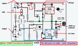
A friend from Brasil, into the Orkut, have bougth those Darlington and wants to build
I have offered him those modifications.
This will turn the amplifier more stable.
To the 18K resistance shown, use a trimpot and adjust the off set, starting with 18K and them tweak.
To avoid oscilations, because of those darlingtons, i suggest the use of 470pf capacitors...this will turn it more stable...BUT, will triangulate the wave shape into high frequencies , into top audio frequencies end.... say... sinusoidal signal enters and into the output appear triangle.
regards,
Carlos
Attachments
ohhh come on carlos !!!!!
make your friend a favour make him a couple of DX bords and he will ove you for the rest of his life ....
a bit of reactive load , the smalest short circuit, some overdrive and any form of abuse will kill this amp ...everybody knows that ...
if this was coming from an amature i would say nothing ....but you ????
just give him some ideas on how to construct a DX and thats it ......
none of the amps i ve seen with this idea ever worked properly un less rail voltage is like 25+25 may be then its possible ....
any way .... my best regards
Yes.... i have informed to the Brazilian friend this amplifier is dangerous
He knows that... my modifications is to avoid the explosion only.
Nobody said it is good.
regards,
Carlos
He knows that... my modifications is to avoid the explosion only.
Nobody said it is good.
regards,
Carlos
Hi everyone,
I have built this amp exactly as shown in the original schema with 30v rails on perf board in sub for my emac with no problems at all. About the only thing i can say is, it is very noisy but that could be because it was my first project and i had no clue as to what i was doing...
I have built this amp exactly as shown in the original schema with 30v rails on perf board in sub for my emac with no problems at all. About the only thing i can say is, it is very noisy but that could be because it was my first project and i had no clue as to what i was doing...
Edsay73...mui bueno, me gusta mucho saber
entonces no hay problemas....bueno!
Very good, i feel happy to know, so, there's no problems...good!
regards,
Carlos
entonces no hay problemas....bueno!
Very good, i feel happy to know, so, there's no problems...good!
regards,
Carlos
Re: Edsay73...mui bueno, me gusta mucho saber
I built it just for the sport ... well, It didn't start at its current condition ! I modified a bit, just using good ol' Rod's Project 03 component calculations, and guess what ... it had no problems with the powering up, and in fact - sounded very well indeed. 😎
See this, but imagine the output stage with darlingtons ... also some other minor changes :
- There was a miller cap only in VAS.
- The bias control circuit was in my case - only 2 pcs 1N4007, no Vbe multiplier. (and that's why it ran cold-blooded at 8mA bias 😀 )
- Power supply rails were +/-42V .... I had no problems at 8 ohms load for about half an hour of playing at maxxed volume - fact, the heatsink was as close to COLD as it could get. 😀 It was just fairly warm...
- Output offset was about 30-40mV or so...pretty good, concidering the parts arent exactly the same as in the circuit. (bootstrap, and base resistor for the first BC - 2k, NFB and input resistance - 18k
Untill .... i decided to make myself a kamakaze mission - and connected another 8 ohm speaker in parallel ... then after about ten minutes of playing : POOF, BANG &#$%@$#^ ...... (smell of fried Si and electrolyte) ...... (deadly silence)
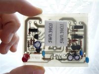
What happened you'll say ... well - these are the heroes :

In your left corner - fake TIP147, in the right - fake TIP142. As you can clearly see - the PNP darlington is a BIG fake, and probably it got loose first with the 4 ohm load, blew, took the other darlington, and beacause of this - dropped about 80V (the two rails) between the bootstrap cap's leads, and taking it with them. (the cap was for 50V)
Here's my test pcb before the blast ... it's sitting there in a lonely corner, waiting for some good darlingtons...and a bootstrap cap. (all other components are OK)

That's it for now from me .... I might come back in this thread, as soon as I find some decent POWER darlingtons ... (not fakes, and weaks like those 😛)
Can you suggest any subtitutes, except the BDW83/84 ?? (they must be in the same case, I don't like TO-3's ... they're hard to mount 😀 )
No problems ... with low voltages and big loads ...destroyer X said:
entonces no hay problemas....bueno!
Very good, i feel happy to know, so, there's no problems...good!
regards,
Carlos
I built it just for the sport ... well, It didn't start at its current condition ! I modified a bit, just using good ol' Rod's Project 03 component calculations, and guess what ... it had no problems with the powering up, and in fact - sounded very well indeed. 😎
An externally hosted image should be here but it was not working when we last tested it.
See this, but imagine the output stage with darlingtons ... also some other minor changes :
- There was a miller cap only in VAS.
- The bias control circuit was in my case - only 2 pcs 1N4007, no Vbe multiplier. (and that's why it ran cold-blooded at 8mA bias 😀 )
- Power supply rails were +/-42V .... I had no problems at 8 ohms load for about half an hour of playing at maxxed volume - fact, the heatsink was as close to COLD as it could get. 😀 It was just fairly warm...
- Output offset was about 30-40mV or so...pretty good, concidering the parts arent exactly the same as in the circuit. (bootstrap, and base resistor for the first BC - 2k, NFB and input resistance - 18k
Untill .... i decided to make myself a kamakaze mission - and connected another 8 ohm speaker in parallel ... then after about ten minutes of playing : POOF, BANG &#$%@$#^ ...... (smell of fried Si and electrolyte) ...... (deadly silence)
What happened you'll say ... well - these are the heroes :
In your left corner - fake TIP147, in the right - fake TIP142.
As you can clearly see - the PNP darlington is a BIG fake, and probably it got loose first with the 4 ohm load, blew, took the other darlington, and beacause of this - dropped about 80V (the two rails) between the bootstrap cap's leads, and taking it with them. (the cap was for 50V)Here's my test pcb before the blast ... it's sitting there in a lonely corner, waiting for some good darlingtons...and a bootstrap cap. (all other components are OK)
That's it for now from me .... I might come back in this thread, as soon as I find some decent POWER darlingtons ... (not fakes, and weaks like those 😛)
Can you suggest any subtitutes, except the BDW83/84 ?? (they must be in the same case, I don't like TO-3's ... they're hard to mount 😀 )
I can realy recommend Carlos's original DX amp in this category..
Low cost.. about $10 to $15 in components, and big power for the money.... can reliably drive 4 ohm loads.
Low cost.. about $10 to $15 in components, and big power for the money.... can reliably drive 4 ohm loads.
o god not again .....
best will be to fit mj11015-16 from on semi ...very good transistor and extremelly good construction ( also cost about 5e a piece in athens )
but when you have so nice transistors whats the point on driving them with such a stupid circuit ...... when so many others available ....
this john fisher amp is cr***ap any way you slice it .....
moderators have to remove it from the forum ....together with the original post ( some one have to remove john fishers post in the first place )
god i have to look for john"s e mail...every now and then we get a post from some one trying to produce power with no components .....
what ever .....
Re: o god not again .....
Very good device indeed, but as I said ... I don't like (HATE) TO-3's. 😀
Besides ... we don't have it here although Athens is close to us, but if I find it in our market - most of the on semi devices are fakes, so .... any other propositions? 😀
Nice specs, and powerfull as well ... 30A, WOW.sakis said:best will be to fit mj11015-16 from on semi ...very good transistor and extremelly good construction ( also cost about 5e a piece in athens )
Very good device indeed, but as I said ... I don't like (HATE) TO-3's. 😀
Besides ... we don't have it here although Athens is close to us, but if I find it in our market - most of the on semi devices are fakes, so .... any other propositions? 😀
- Status
- Not open for further replies.
- Home
- Amplifiers
- Solid State
- Cheap 100 to 150 Watt Amp