I almost know you are right, because I have right now a class of students in their 40-50 with mental handicaps who has never got the chance of learning to read, and it is possible. If you can not learn to read, is it not you but the teacher who are at fault. Everybody can learn to read!!That’s one possible scenario.
Another possibility is that such tools become good enough to teach with infinite patience and care. Hence, people who could not acquire the knowledge and skills to be useful contributor in their field suddenly can and human-driven progress continues or accelerates.
Are you able to read your own name then can you already read a bit, if you are not able to do that, then is it a great place to start. 🙂

I could not leave my ChatGPT project just hanging, so I changed the rules a bit and this time was I allowed to ask leading questions and argue my case, but I was still not allowed to place any components that ChatGPT did not accept as "a great idea"
I would like for you to look for errors, I am not sure if it in fact will work correctly.
I would like for you to look for errors, I am not sure if it in fact will work correctly.
Attachments
IMHO there's something fundamentally backwards about trying to use ChatGPT to design something for you that you do not understand only to have to ask a group of "real" people to actually make sure it works... I've seen the same with code where people get generated code which they are then unable to troubleshoot when it doesn't work.
Why don't you sim the circuit or build it IRL to see if it works? If you don't know how to do either those things, there's a wonderful learning opportunity where you'll actually end up with at least one usable skill that you can make use of in the future 😎
Also I don't understand why someone would think that an LLM can "design" a circuit? From everything I read and understand the only thing it can "design" is plausible-sounding answers to your questions - which is pretty darned far from actually designing a circuit (or anything else for that matter).
I am sorry, I may have been very unclear in what I have written. I can easily understand your reaction and your thoughts.
I'll try to formulate my question a bit better🙂
Is this a sane way to design the circuit, I know my constraints did some of it, but I do not think I have seen a design like that before.
I am not unsure about noise, but I am unsure about its performance, "if it will work", meaning is it pure stupid or is there some sanity behind?
An op-amp with an VCR in the feedback with a buffer and a pot. Will it work correctly, as a "damaged pot does not influence the sound"?
Edit: I have tried to simulate some of it and LtSpice, and I was not cooperating so I did not get anything out of that.
I don't seem to get the purpose of this experiment...
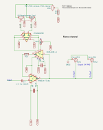
Anyway, circuit won't work at all, for very obvious reasons:
Anyway, circuit won't work at all, for very obvious reasons:
- OpAmp has no bias
- VCA is hooked up completely wrong. This is a current input/output device with input and output at to operated virtual GND, so an AC-coupled resistor must be used as V/I and an opamp as I/V. Hence, no DC feedback and the polarity is inverted, too... wrong way...
I'm still quite impressed... the AI must have been using a tool to draw this? Or did it find these schematics in a dark corner of the internet? If it indeed started up the tool, drew the components and took the requirement into consideration, it is quite a feat for a "machine" in its infancy.
//
//
The drawing is unfortunately made by me, from description and some primitive drawings on ChatGPT.
I am also a bit impressed because the AI did all that from different text documents and managed to combine across the articles it has been trained on.
I am also a bit impressed because the AI did all that from different text documents and managed to combine across the articles it has been trained on.
I am not sure if I understand your comment?I don't seem to get the purpose of this experiment...
Anyway, circuit won't work at all, for very obvious reasons:
- OpAmp has no bias
- VCA is hooked up completely wrong. This is a current input/output device with input and output at to operated virtual GND, so an AC-coupled resistor must be used as V/I and an opamp as I/V. Hence, no DC feedback and the polarity is inverted, too... wrong way...
Could you please add some details to make it easier to get hold on?
Nice, perhaps not bad for parroting software. But only human does design not knowing basics.I am not sure if I understand your comment?
Could you please add some details to make it easier to get hold on?
"I am an artist, that the way I see it."
- Home
- Amplifiers
- Solid State
- ChatGPT designed a gain cell - your comments?