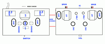
I'm looking to redo my 2A3 SET chassis. This time I'm thinking 2 separate enclosures for better isolation. I use 105 db horn drivers so low hum or buzz is critical.
Here's the layout.
Any suggestions? Thanks.
Here's the layout.
An externally hosted image should be here but it was not working when we last tested it.
Any suggestions? Thanks.
Depending on topology you might want to move both pairs. Placing them on chassis from the audio stages effectively adds 24" (?) of wire in each direction, B+ supply and ground return. That wire adds an order of magnitude or more of inductance and resistance to the cap and scotches two benefits of what appear to be nice oval oils. By keeping that loop tight you're also much less likely to run into high frequency oscillation issues, hum, etc. . The actual placement on the audio chassis was just an aesthetic guess, close is all that counts. If you prefer not to move either consider large, high quality local bypasses right at the audio circuit.
That drawing is the layout planned for an 813SE on my bench, the reason it was ready for suggestion.
That drawing is the layout planned for an 813SE on my bench, the reason it was ready for suggestion.
I see your point. Yes, those are motor run oil caps.rdf said:what appear to be nice oval oils. By keeping that loop tight you're also much less likely to run into high frequency oscillation issues, hum, etc. .
Thanks.
- Status
- This old topic is closed. If you want to reopen this topic, contact a moderator using the "Report Post" button.
