Ah, OK, that changes things a little bit! (A lot actually!)
A single 5687 is a bit of a limiting factor in terms of voltage swing, but it is also a lot easier to get the power supply really quiet with a tube that draws so little current so you can use a smaller step-down ratio.
You do not have enough B+ to switch to CCS loading, hopefully you can feed about 250V to the CCS that would load the 5687?
The GXSE15 is such a monster compared to what you actually need, especially once you change the amp to be CCS loaded with the parallel feed cap. Yes, you can use the GXSE, but you should consider getting a pair of XSM 15K:600 transformers instead. They will have no air gap, are far smaller, and will perform really well compared to the GXSE in this instance.
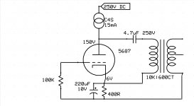
For the bias voltage you have, the gain of the 5687, and what you want at the output, the 5:1 step-down ratio is sensible. Your power supply rail will need to be really well filtered, but I see there that you are using a regulator, so that should work nicely.
A single 5687 is a bit of a limiting factor in terms of voltage swing, but it is also a lot easier to get the power supply really quiet with a tube that draws so little current so you can use a smaller step-down ratio.
You do not have enough B+ to switch to CCS loading, hopefully you can feed about 250V to the CCS that would load the 5687?
The GXSE15 is such a monster compared to what you actually need, especially once you change the amp to be CCS loaded with the parallel feed cap. Yes, you can use the GXSE, but you should consider getting a pair of XSM 15K:600 transformers instead. They will have no air gap, are far smaller, and will perform really well compared to the GXSE in this instance.
For the bias voltage you have, the gain of the 5687, and what you want at the output, the 5:1 step-down ratio is sensible. Your power supply rail will need to be really well filtered, but I see there that you are using a regulator, so that should work nicely.
If I need 250V for CCS I can't get it with the actual power tx 150VAC.
It's needed the output cap between the CCS & anode to the opt? What value to start from?
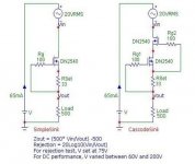
For CCS it's better cascode or single DN2540 also I have LND150 my target 15mA?
Worth the work parallel other triode so using 2 triodes per channel?
It's needed the output cap between the CCS & anode to the opt? What value to start from?
For CCS it's better cascode or single DN2540 also I have LND150 my target 15mA?
Worth the work parallel other triode so using 2 triodes per channel?
Last edited:
Yes, you need a cap between the anode and the OPT. I would start with 20uF.
A cascode CCS is a good choice.
If you paralleled triodes, you could use an even lower step-down ratio if you wanted, so maybe a 10K:600 transformer instead of a 15K:600 transformer. I would just stick with a single triode for now, as the paralleled triodes will also require more current through your CCS, which means more heat.
You can go back to the curves and draw a 15K load line, then look at where the load line hits 0mA to get an idea of how much voltage swing you could get. With 100V on the plate, I assumed that the most possible voltage swing you could have was +/-100V, and I added a little extra for CCS compliance and line voltage variation.
HD650 are quoted as about 100dB/mW or 105dB/V.
From my earlier experiments I managed to get 60mW from a 2 stage amp using tiny triode wired pentodes, which should be good for about 115 dB SPL
In my case, a cascode CCS anode load using DN2540, gave a output Z of around 200k, assuming my measurements werent screwy. CCS current is only about 10mA.
Output impedance is the sticking point, being about 180R at the secondary.
I dropped about 1/3rd B+ across the CCS, when B+ = 150V. Output swing was in the range of 30V RMS into primary wdg, with N=6 OPT. These numbers jive pretty nicely with Edcore XSM but not WSM (if I havent mixed those two models)
While this doesnt match you tubes, which would probably perform better especially in regards to output impedance, perhaps a help to envisage what drive you might desire in your amplifier.
Last edited:
But the load isn't 7.5K because the half reflected impedance to primary using 300 ohms load?
Yes, that's true with the GXSE, as there is no center tap on the winding.
With the XSM 15K:600, you would have a 600 ohm output and a 150 ohm output.
Still the rp of the 5687 is more than adequate to drive a 7.5K load.
Yes, just be aware that voltage doublers demand significant AC current from the power transformer.
Apologies Merlin...
Without looking at schematic I posted my reply.
I got the impression you werent using the OPT in series connection but parafeed.
Sorry if my reply was Off topic or irrelevant
Without looking at schematic I posted my reply.
I got the impression you werent using the OPT in series connection but parafeed.
Sorry if my reply was Off topic or irrelevant
Apologies Merlin...
Without looking at schematic I posted my reply.
I got the impression you werent using the OPT in series connection but parafeed.
Sorry if my reply was Off topic or irrelevant
No needs to ask apologies.
You are always welcome.
OK understood, you want to increase the Bias to 150V.
Could I use cathode resistor 470R & 15k 600R not CT?
Could I use cathode resistor 470R & 15k 600R not CT?
So Merlin el mago you are using parafeed, after all?
Confused 😀
Audiowize posted circuit, is essentially what I have, using different tubes, and should get you close to where you want to be.
I only found it necessary to use C = 0.68uF.
I suspect this is due to the rp of the particular tubes I used, which I calculated had a Rp of about 8k.
All anecdotal 'evidence', i still.need to spend time listening to decide if output impedance (180R), or damping factor (1-2) needs to be improved
Ok, that's good too!
although Auduowize's schematic, has made me realise I may have returned the cold end of the OPT primary to the wrong place...(ground instead of cathode)
although Auduowize's schematic, has made me realise I may have returned the cold end of the OPT primary to the wrong place...(ground instead of cathode)
This is what I would aim for.
Will sound better? Or better to try parallel 5687?
Last edited:
- Home
- Amplifiers
- Tubes / Valves
- Changing triode load