If this was a more modern radio using 7 pin miniature tubes, I'd swap out a 6BE6 and a 6BA6 with 3BE6 and 3BA6 respectively. I don't think they made a 3SA7 or 3SF7. I'd leave their grounded heater pins tied to ground, preserving the RF bypassing as designed and built. And rewire the heater lines so the rest of the set's tubes' heaters are not grounded, and still fed by the 6.3VAC heater winding. And connect one side of the heater winding supply to the 3BE6 and the other to the 3BA6. The 3BE6 and 3BA6, effectively in series with the midpoint grounded, form a voltage divider to create a centertap to make both heater supply windings look like 3.15VAC above ground.
Thanks for the comment wa2ise...I don't think I got any of that, neat idea or not!?....LOL
This is certainly not a "modern radio". And maybe now I'm realizing I'm on a forum here that isn't really geared as much to vintage restoration tips and techniques as it is to experimentation and new designs.
Always curious and interested in gaining understanding though.
I can imagine there are all kinds of better AM radio tube circuit designs out there beyond this one. Not that I won't now do some research on these things you've mentioned.
I am currently looking at some minor and apparently marginal improvements to the existing schematic that really doesn't require any re-design....I seem to be getting more advice to the contrary and to not bother...which is fine also, but maybe this is another case of confusion as to what I'm posting and who's commenting on them.
If this unit is rare or valuable then it might not be a good vehicle for initial learning about valve radio or audio. Bear in mind that any changes apart from sympathetic repairs could destroy its value. Up to you, but you might be better to start with something common and cheap. Lots of old radios available. Then come back to this when you have more experience.
Not really that rare or valuable, even if I was to sell it, which I probably won't. I think I've seen one of these on ebait for under a couple hundred $$. They were a pretty common recording type machine in the 40's before tape.
I have debated on changing things and that is part of my back and forth.
But I have lots of time on my hands and this was something my Dad owned who passed away recently and has now come into my personal possession. It hadn't been seen, used or worked in many, many years, probably 20 to 30 years at least collecting dust. I wasn't even aware of it's existence until I uncovered it going through my Dad's things in the attic!
This is by far the oldest and most unique object I've made into a project and my background has been in solid state and digital all my life. The last tube object I remember being around was an old 25" color console TV set a long time ago. I can even remember helping my grandfather change and taking tubes downtown on the bus when I was a little kid..so there's some real history with all this! It's funny how both my Dad and grandfather were quite involved with the tube gear back then and how far away from that I've gotten...so a lot of this is a "way back machine"....😀
And I truly am debating between just getting it going and keeping it vintage, no doubt. I guess I'm taking extra care and caution just because it would be cool to get it working nicely and as a matter of personal enjoyment, I dont' mind spending some money on fixing it nicely. I'm actually enjoying this activity. But safe and sane is always a good thing with me.
Interestingly....I do have an old Northern Electric 2500 tabletop radio that needs the same kind of loving care, but this Meissner machine has recording functions, a record cutter as well as the radio and phono so it's generated way more interest for me. I do plan on fixing the radio in the future.
One thing is I have some old recordings made on this thing that I want to listen to, which may have my Dad and grandparents voice on it. That is something I would like to capture digitally on my own modern digital recording system!!....🙂
All things considered I will make it operate electrically in a modern and safe fashion and leave the circuitry design as is with a grounded chassis. I think the heater deal is interesting, but a waste of time and effort and like you said may create a mess of things.
I'll post some more photos as I make progress and let you all know how it goes.
Thanks for the help and advice!
DJ
Well little dilemma has cropped up and I need some help and understanding.
🙂
This amp has a tone control pot that is not shown on the schematic and it's unclear where and how this goes in the circuit.
From my photos and documentation it seems this was missed in the drawing.
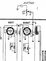
The "tone" control is part of the main power switch and located beneath the switch section on the same shaft.
The pot is a three leg 25k pot and after you switch the unit on the rest of the rotation becomes the "tone" control. I think it is for adding brightness to your recordings at the output to the cutter head.
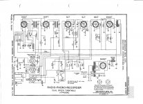
So only two legs are connected on this pot. One end of the pot is NC. The other end of the pot goes to a .05uf/400V cap the other end of which goes to chassis ground.
The wiper of that pot (center tab) goes to the plate (pin 3) of the 6V6GT output tube via a shielded conductor (I think).
That pin 3 also wires to the audio output transformer and a .01uf/1000V cap the other end of which is chassis grounded. I've attached the schematic again for reference, but you won't find this tone control circuit on there....
I'm hoping some tube circuit guru will recognize this type of tone circuit and confirm that the wiper is going to the correct tube and pin location.
Any tone/brightness/tilt circuits I have found online seem to go at the preamp or driver stage tube, so that is part of my misunderstanding and confusion.
I would also like to understand how that works in the circuit and how it alters the "brightness"....
🙂
This amp has a tone control pot that is not shown on the schematic and it's unclear where and how this goes in the circuit.
From my photos and documentation it seems this was missed in the drawing.
The "tone" control is part of the main power switch and located beneath the switch section on the same shaft.
The pot is a three leg 25k pot and after you switch the unit on the rest of the rotation becomes the "tone" control. I think it is for adding brightness to your recordings at the output to the cutter head.
So only two legs are connected on this pot. One end of the pot is NC. The other end of the pot goes to a .05uf/400V cap the other end of which goes to chassis ground.
The wiper of that pot (center tab) goes to the plate (pin 3) of the 6V6GT output tube via a shielded conductor (I think).
That pin 3 also wires to the audio output transformer and a .01uf/1000V cap the other end of which is chassis grounded. I've attached the schematic again for reference, but you won't find this tone control circuit on there....
I'm hoping some tube circuit guru will recognize this type of tone circuit and confirm that the wiper is going to the correct tube and pin location.
Any tone/brightness/tilt circuits I have found online seem to go at the preamp or driver stage tube, so that is part of my misunderstanding and confusion.
I would also like to understand how that works in the circuit and how it alters the "brightness"....
Attachments
Here's another problem I've discovered!
Man this seems to be turning into a kluge...maybe why this wasn't working, collecting dust and had blown caps!
The schematic and original wiring for the (2) 6J7's which is the mixer section had 6SJ7GT tubes plugged in there.
When I went to double check the schematic against those tubes the pinout was completely different than a 6J7. The plate on a 6J7 is pin 3. On a 6SJ7GT the plate is on pin 8!
Any idea what that would have done to it?
Seems like I have to rewire this to the 6SJ7GT or get some 6J7 or 6J7GT's which I believe may be hard to find. Now I have no way to test the tube or the circuit wiring!!
Advice please?
I'm starting to pull my hair out!....and my brain is spinning!
If possible, I would certainly want to use the original tube types.
So first, I would check for their availability. Perhaps there is even a modern equivalent, or a viable substitute new or old. Or maybe the Soviets are still making them.
So first, I would check for their availability. Perhaps there is even a modern equivalent, or a viable substitute new or old. Or maybe the Soviets are still making them.
Verify that it isn't already wired for the 6SJ7.. A number of American manufacturers made undocumented running changes from 6J7 to 6SJ7 perhaps due to a supply or discontinuance issue way back.
Chances are the 6SJ7 are not there by accident and the circuit was wired for them. Don't panic. Check where to connections go if you are not sure.
You probably do not have the correct schematic for the unit you have although it may be generally correct.
Chances are the 6SJ7 are not there by accident and the circuit was wired for them. Don't panic. Check where to connections go if you are not sure.
You probably do not have the correct schematic for the unit you have although it may be generally correct.
It turned out that was the case. The schematic had old original pinouts and hookup for the 6J7 tube, but like you said they revised those to 6SJ7GT's including the wiring to the socket. I just didn't look at the wiring and pins carefully enough to see it was wired correctly. So I think I'm back on track.
I found the 6J7 was discontinued quite a while back!
Of course this is a 65+ year old radio/phonograph so I'm trying to check everything and replace as much as I can...
I found the 6J7 was discontinued quite a while back!
Of course this is a 65+ year old radio/phonograph so I'm trying to check everything and replace as much as I can...
I bought (2) 15uf 450V electrolytic caps to replace the 15+15uf 450V can cap.
They are very small sized and one of them is slightly smaller in length than the other one. The longer one measures 16uf and the shorter one measures 13uf with my Fluke meter.
Here are the specs:
15 UF 450 VDC 105 degree C Radial Electrolytic Capacitors. Standard polarized type with long leads, ideal for recaps of vintage radios, TV's, guitar amps, and audio equipment. SPECIFICATIONS: Working Voltage: 450 VDC Surge voltage: 500 VDC Capacitance Tolerance: +/- 20% Operating temperature: -40C to +105C. Dissipation Factor: <0.24 @ 20C/120Hz Dimensions: 13mm by 21mm (1/2" by 7/8") Lead type and length: Tinned copper-ply, 40mm (1.5") Type: Polarized Manufacturer & Series: MIEC KR.
Are these OK to use? They seem so small compared to the big can?
Just looking to get some reassurance.
I'm also wondering if I need to install a bleed resistor.
This didn't have one before, so I'm sort of leaning to not adding something like that if not needed.
Greetings from FixitLand!
The 6J7 and 6SJ7 are functionally identical (both are sharp-cutoff pentodes), but they differ in pinout as you found. 6J7 is a top-cap tube (G1 is brought to the cap) while 6SJ7 is "single-ended" (thus the 'S') and has all connections at the base. So if your schematic is showing 6J7 but the set has 6SJ7 and no wire to a top-cap connector, you can figure the set has been modified/updated.
That's a Wilcox-Gay Recordio-type recording machine, likely using an Astatic X-26 crystal cutterhead or something very similar. I have one as well; it had a cracked crystal and was inoperative. Believe it or not, in 1981 I could still purchase a replacement *brand-new*...that's no longer the case unless you happened to stumble upon NOS parts somewhere. West-Tech Services rebuilds those heads, as well as the crystal playback cartridge. Don't expect hi-fi miracles with this gear. Another item you may have to search for is a recording stylus...these rigs usually used plain steel cutting needles which lasted maybe 10 or 12 minutes before getting dull and noisy. A jeweled recording stylus would be expensive overkill. Perhaps a tool shop could make up a carbide-tipped stylus that might last a while but that too would be expensive. I'm not sure if West-Tech handles the styli.
Take care,
--
J. E. Knox "The Victor Freak"
Greetings from FixitLand!
105-degree rating is good. I'm not thrilled to see a new cap measure below spec, but electrolytics are usually -20/+80% tolerance so it's not too bad. The smaller size is typical of modern components compared to vintage ones. Consider, too, that putting in a replacement 16-16uF 450V can cap from AES would have run you $10 plus shipping (and add the cost of a clamp), or a 20-20uF 450V FP-type cap (likely similar to the original part) would have set you back $31 plus shipping (ouch!). And these aren't 105-degree-rated.
A bleed resistor isn't a bad idea if there's not one in the circuit now. At power-down, the audio power amp will draw the supply down quite a ways as the tube cools, but there could be 25 to 50 V or more still present some time after shutdown. A 220K 1/2W or 1W resistor will suffice, and draws 1 mA at 220 V B+ (if that is a problem, even a 470K resistor would do well for the purpose).
Take care,
--
J. E. Knox "The Victor Freak"
I bought (2) 15uf 450V electrolytic caps to replace the 15+15uf 450V can cap.
They are very small sized and one of them is slightly smaller in length than the other one. The longer one measures 16uf and the shorter one measures 13uf with my Fluke meter. ...
Are these OK to use? They seem so small compared to the big can?
Just looking to get some reassurance.
I'm also wondering if I need to install a bleed resistor.
This didn't have one before, so I'm sort of leaning to not adding something like that if not needed.
105-degree rating is good. I'm not thrilled to see a new cap measure below spec, but electrolytics are usually -20/+80% tolerance so it's not too bad. The smaller size is typical of modern components compared to vintage ones. Consider, too, that putting in a replacement 16-16uF 450V can cap from AES would have run you $10 plus shipping (and add the cost of a clamp), or a 20-20uF 450V FP-type cap (likely similar to the original part) would have set you back $31 plus shipping (ouch!). And these aren't 105-degree-rated.
A bleed resistor isn't a bad idea if there's not one in the circuit now. At power-down, the audio power amp will draw the supply down quite a ways as the tube cools, but there could be 25 to 50 V or more still present some time after shutdown. A 220K 1/2W or 1W resistor will suffice, and draws 1 mA at 220 V B+ (if that is a problem, even a 470K resistor would do well for the purpose).
Take care,
--
J. E. Knox "The Victor Freak"
Greetings from FixitLand!
105-degree rating is good. I'm not thrilled to see a new cap measure below spec, but electrolytics are usually -20/+80% tolerance so it's not too bad. The smaller size is typical of modern components compared to vintage ones. Consider, too, that putting in a replacement 16-16uF 450V can cap from AES would have run you $10 plus shipping (and add the cost of a clamp), or a 20-20uF 450V FP-type cap (likely similar to the original part) would have set you back $31 plus shipping (ouch!). And these aren't 105-degree-rated.
A bleed resistor isn't a bad idea if there's not one in the circuit now. At power-down, the audio power amp will draw the supply down quite a ways as the tube cools, but there could be 25 to 50 V or more still present some time after shutdown. A 220K 1/2W or 1W resistor will suffice, and draws 1 mA at 220 V B+ (if that is a problem, even a 470K resistor would do well for the purpose).
Take care,
--
J. E. Knox "The Victor Freak"
Thanks JE for checking my choice. These were described as tube radio filter cap replacements, so I was just double checking. The specs seem to confirm they're OK. I'm learning good stuff here.
The rectifier tube I have in this is a 5Y3 with a 600 ohm speaker field coil as the choke and the original can cap was a 20uf+20uf. The schematic called out 15uf's so that was what I ended up getting. The voltage chart lists 260VDC for the B+. So I will see if those do the job and measure out the correct B+ voltage at that last filter cap. I've measured the primary transformer with no load and it all looked good. 320-0-320 which is exactly what the voltage chart lists.
Sorry if this all seems anal retentive but I'm just trying to be careful, take my time. I'm a safe and sane person who takes a lot of cautions. So I really appreciate all your experienced comments.
I have some new 200k 1/2W carbon comp resistors I could use as a bleed resistor. The spec sheet says they are good to 350-400V with an overlimit of 500V. So that sounds like it would be safe. My calculation came up with 260VDC @ 200k to be 0.34W at that last 15uf cap.
Greetings from FixitLand!
The 6J7 and 6SJ7 are functionally identical (both are sharp-cutoff pentodes), but they differ in pinout as you found. 6J7 is a top-cap tube (G1 is brought to the cap) while 6SJ7 is "single-ended" (thus the 'S') and has all connections at the base. So if your schematic is showing 6J7 but the set has 6SJ7 and no wire to a top-cap connector, you can figure the set has been modified/updated.
That's a Wilcox-Gay Recordio-type recording machine, likely using an Astatic X-26 crystal cutterhead or something very similar. I have one as well; it had a cracked crystal and was inoperative. Believe it or not, in 1981 I could still purchase a replacement *brand-new*...that's no longer the case unless you happened to stumble upon NOS parts somewhere. West-Tech Services rebuilds those heads, as well as the crystal playback cartridge. Don't expect hi-fi miracles with this gear. Another item you may have to search for is a recording stylus...these rigs usually used plain steel cutting needles which lasted maybe 10 or 12 minutes before getting dull and noisy. A jeweled recording stylus would be expensive overkill. Perhaps a tool shop could make up a carbide-tipped stylus that might last a while but that too would be expensive. I'm not sure if West-Tech handles the styli.
Take care,
--
J. E. Knox "The Victor Freak"
It's close....it's a Meissner 9-1065. It has the Astatic X-26 cutter head and Astatic L40A phono cartridge.
I have 2 new cutter needles that look like machined tips. (probably carbide) One of them is still in this nifty little screw case. I also have a ton of those straight steel needles.
As far as getting all that working I've remounted the rubber pads on the turntable motor and tested it with 120VAC and it seems to be strong and works well. The spiral shaft rod underneath the platter all works with the cutter arm. Until I get the amp chassis all put back together I won't be able to test anything else. I'm not optimistic on either of those crystal cartridges working though. I may drill out the rivets though just to take a look inside.
And I'm thinking about trying to replace the crystal with a piezo element which I've seen done online.
As far as the phono tonearm, I've been looking at replacement ceramic cartridges for that. They don't appear too expensive for a 2 hole mount "flip" cartridge that will play 78 and flip to 33-1/3. Too bad it won't play 45's.....
There are a number of ceramic pickups that support 78, 45 and 33⅓ RPM. by flipping them over. Sonotone comes immediately to mind.
Greetings from FixitLand!
Glad to help. There are lots of folks here with good info.
Schemo showed 15 uFs but unit had 20 uFs? Hmmm. It will work, but you *may* have increased hum. 20s or 22s would be better.
That's a good thing!
200K is a tad low, and 0.34 W (340 mW) is a bit tight to run a 1/2-watt carbon resistor. Better to go with a 1-watt, or a higher resistor value. You could also tie two of those 200Ks in series; that would work fine and impose half the load on the power supply.
That's the unit model number. The turntable assembly itself is identical to those used by Wilcox-Gay, some Wards Airline and other home recorders. I'm not sure if Wilcox-Gay manufactured them or some other outfit; that's why I called it a "Wilcox-Gay Recordio-type" unit. It could have been built for Meissner by Wilcox-Gay. Does it run at 33-1/3 and 78 rpm? Mine (an Airline) does.
Chances are the cutters are not carbide. The tips are indeed machined, to a specific shape (the packaging on some styli details the angles; that data escapes me at the moment). The "straight steel needles" are for playback only, and in fact are intended for **single-use only**! Don't trust them to be usable; people had a tendency to keep used needles. Why, I have no idea. Re-using a steel needle is DEATH to records. For that matter, a steel needle is DEATH to a home-recorded lacquer disc, too! Replacing the playback crystal cartridge with a modern ceramic unit (you mention below)...a good idea. Even better would be to NOT use this unit for playing back home recordings. They are much softer than regular records and won't last long. It would at least be necessary to counterbalance the tone arm for the modern cartridge.
DON'T!!!!! You will ruin the likelihood of West-Tech being able to restore the cutterhead. (I had the same idea years ago, and I've regretted it ever since.)
A crystal *IS* a piezo element. Really -- DON'T mess with the Astatic cutterhead; leave it to West-Tech if it's not working. You should feel definite vibration at the cutting stylus with recording signal applied (you don't have to actually record and waste a disc to test this).
OKeh, you *do* have a two-speed unit...and yeah, it is annoying not to have 45. One thing about installing a flipover cartridge is that you have to be sure the flip arm clears the underside edge of the tone arm; otherwise, the stylus won't be at the proper angle and it'll turn your music collection into "wreck-ords."
Take care,
--
J. E. Knox "The Victor Freak"
Thanks JE for checking my choice. These were described as tube radio filter cap replacements, so I was just double checking. The specs seem to confirm they're OK. I'm learning good stuff here.
Glad to help. There are lots of folks here with good info.
The rectifier tube I have in this is a 5Y3 with a 600 ohm speaker field coil as the choke and the original can cap was a 20uf+20uf. The schematic called out 15uf's so that was what I ended up getting. ...
Schemo showed 15 uFs but unit had 20 uFs? Hmmm. It will work, but you *may* have increased hum. 20s or 22s would be better.
Sorry if this all seems anal retentive but I'm just trying to be careful, take my time. I'm a safe and sane person who takes a lot of cautions. ...
That's a good thing!
I have some new 200k 1/2W carbon comp resistors I could use as a bleed resistor. The spec sheet says they are good to 350-400V with an overlimit of 500V. So that sounds like it would be safe. My calculation came up with 260VDC @ 200k to be 0.34W at that last 15uf cap.
200K is a tad low, and 0.34 W (340 mW) is a bit tight to run a 1/2-watt carbon resistor. Better to go with a 1-watt, or a higher resistor value. You could also tie two of those 200Ks in series; that would work fine and impose half the load on the power supply.
It's close....it's a Meissner 9-1065. It has the Astatic X-26 cutter head and Astatic L40A phono cartridge.
That's the unit model number. The turntable assembly itself is identical to those used by Wilcox-Gay, some Wards Airline and other home recorders. I'm not sure if Wilcox-Gay manufactured them or some other outfit; that's why I called it a "Wilcox-Gay Recordio-type" unit. It could have been built for Meissner by Wilcox-Gay. Does it run at 33-1/3 and 78 rpm? Mine (an Airline) does.
I have 2 new cutter needles that look like machined tips. (probably carbide) One of them is still in this nifty little screw case. I also have a ton of those straight steel needles.
Chances are the cutters are not carbide. The tips are indeed machined, to a specific shape (the packaging on some styli details the angles; that data escapes me at the moment). The "straight steel needles" are for playback only, and in fact are intended for **single-use only**! Don't trust them to be usable; people had a tendency to keep used needles. Why, I have no idea. Re-using a steel needle is DEATH to records. For that matter, a steel needle is DEATH to a home-recorded lacquer disc, too! Replacing the playback crystal cartridge with a modern ceramic unit (you mention below)...a good idea. Even better would be to NOT use this unit for playing back home recordings. They are much softer than regular records and won't last long. It would at least be necessary to counterbalance the tone arm for the modern cartridge.
As far as getting all that working I've remounted the rubber pads on the turntable motor and tested it with 120VAC and it seems to be strong and works well. The spiral shaft rod underneath the platter all works with the cutter arm. Until I get the amp chassis all put back together I won't be able to test anything else. I'm not optimistic on either of those crystal cartridges working though. I may drill out the rivets though just to take a look inside.
DON'T!!!!! You will ruin the likelihood of West-Tech being able to restore the cutterhead. (I had the same idea years ago, and I've regretted it ever since.)
And I'm thinking about trying to replace the crystal with a piezo element which I've seen done online.
A crystal *IS* a piezo element. Really -- DON'T mess with the Astatic cutterhead; leave it to West-Tech if it's not working. You should feel definite vibration at the cutting stylus with recording signal applied (you don't have to actually record and waste a disc to test this).
As far as the phono tonearm, I've been looking at replacement ceramic cartridges for that. They don't appear too expensive for a 2 hole mount "flip" cartridge that will play 78 and flip to 33-1/3. Too bad it won't play 45's.....
OKeh, you *do* have a two-speed unit...and yeah, it is annoying not to have 45. One thing about installing a flipover cartridge is that you have to be sure the flip arm clears the underside edge of the tone arm; otherwise, the stylus won't be at the proper angle and it'll turn your music collection into "wreck-ords."
Take care,
--
J. E. Knox "The Victor Freak"
That link didn't work item had ended...
There are a number of ceramic pickups that support 78, 45 and 33⅓ RPM. by flipping them over. Sonotone comes immediately to mind.
Thanks JonSnell....I've seen a couple places online that sell ones that look like they would fit the tonearm I have here has a 2 hole bracket.
I would probably rewire with new shielded cable and make sure it is compatible with the input tube stage.
I'll check out Sonotone
Greetings from FixitLand!
Glad to help. There are lots of folks here with good info.
Schemo showed 15 uFs but unit had 20 uFs? Hmmm. It will work, but you *may* have increased hum. 20s or 22s would be better.
200K is a tad low, and 0.34 W (340 mW) is a bit tight to run a 1/2-watt carbon resistor. Better to go with a 1-watt, or a higher resistor value. You could also tie two of those 200Ks in series; that would work fine and impose half the load on the power supply.
That's the unit model number. The turntable assembly itself is identical to those used by Wilcox-Gay, some Wards Airline and other home recorders. I'm not sure if Wilcox-Gay manufactured them or some other outfit; that's why I called it a "Wilcox-Gay Recordio-type" unit. It could have been built for Meissner by Wilcox-Gay. Does it run at 33-1/3 and 78 rpm? Mine (an Airline) does.
Chances are the cutters are not carbide. The tips are indeed machined, to a specific shape (the packaging on some styli details the angles; that data escapes me at the moment). The "straight steel needles" are for playback only, and in fact are intended for **single-use only**! Don't trust them to be usable; people had a tendency to keep used needles. Why, I have no idea. Re-using a steel needle is DEATH to records. For that matter, a steel needle is DEATH to a home-recorded lacquer disc, too! Replacing the playback crystal cartridge with a modern ceramic unit (you mention below)...a good idea. Even better would be to NOT use this unit for playing back home recordings. They are much softer than regular records and won't last long. It would at least be necessary to counterbalance the tone arm for the modern cartridge.
DON'T!!!!! You will ruin the likelihood of West-Tech being able to restore the cutterhead. (I had the same idea years ago, and I've regretted it ever since.)
A crystal *IS* a piezo element. Really -- DON'T mess with the Astatic cutterhead; leave it to West-Tech if it's not working. You should feel definite vibration at the cutting stylus with recording signal applied (you don't have to actually record and waste a disc to test this).
OKeh, you *do* have a two-speed unit...and yeah, it is annoying not to have 45. One thing about installing a flipover cartridge is that you have to be sure the flip arm clears the underside edge of the tone arm; otherwise, the stylus won't be at the proper angle and it'll turn your music collection into "wreck-ords."
Take care,
--
J. E. Knox "The Victor Freak"
I will think about getting bigger caps, 22uf 450V might be a better filter for sure.
The bleed resistor I will find something with more watts.
I have 22k 2W but I think that might be too low.
What voltage should you use to calculate that?
260VDC is the B+ number is that the one to use?
If I get this thing working and the radio picks up something in the AM, I'll be doing good. Getting the turntable, cutter and phono playback going will be a whole other story and milestone. I won't do anything with those until I see whats up.
And as far as using it for anything good that is not a problem....I'm sure it won't have the greatest sound. I think at this point it will mostly be a novelty object...
This was something I thought might be fun and easy to restore but I have very little expectation for anything. It is a great tube learning unit though because it has everything in there, mic's, phono, radio, amplifier..
I think it's pretty cool....
Can someone explain to me how this "tone" control actually works in the circuit. As you can see in my scan it's a 25k pot with the wiper connected via shielded conductor to the plate of the 6V6GT tube with one end of the pot thru a .05uf/400V cap to ground. I also noticed they grounded the shield over the plate/wiper wire to chassis ground at both ends?? Was that common practice in those days?
This is the description from the manual about the tone control usage:
TONE CONTROL WHEN RECORDING
"The setting of the tone control when recording is partly a matter of choice and preference of the operator, but it might well be pointed out here that usually the most satisfying factory recordings are made with the tone control turned to the counter clockwise position. There are exceptions to this, and the operator after a little experience in handling the equipment will learn what setting of the tone control is required for any particular set of conditions"
After reading that I'm wondering if the tone control only works with the cutter head part of the circuit (recording) and has no effect on the radio tone or the phono playback tone??
Thanks for any help in understanding!
Attachments
No help or explanation from anyone?
Is this an incorrect connection?
This tone control was something not shown on the schematic..so I'm just trying to confirm and understand it's operation...
Thanks for any comments
Is this an incorrect connection?
This tone control was something not shown on the schematic..so I'm just trying to confirm and understand it's operation...
Thanks for any comments
- Status
- Not open for further replies.
- Home
- Amplifiers
- Tubes / Valves
- Changing to twisted pair heater from one side grounded