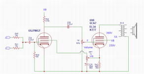
I am thinking about building a Champ 5C1 clone based on a schematic mod I found which added NFB to the circuit almost like a gain pot. There was an audio file where he played the amp and demonstrated it and I got the schematic from him a while ago. I want to build it so I have multiple tube options as listed in the attached schematic.
Before I dig into this I wanted to see what you all think about the viability of this, I assume they are not all simply just drop in replacements, even though I see them called equivalents, and some switching may be necessary to set bias and other levels appropriately.
Before I dig into this I wanted to see what you all think about the viability of this, I assume they are not all simply just drop in replacements, even though I see them called equivalents, and some switching may be necessary to set bias and other levels appropriately.
Attachments
I have been wondering about that (Biased at 0) but, I checked the Champ 5C1 schematic and that is what it says. Every one I look at.
As for G2 does anyone know what that voltage is based on the original Fender schematic? There is 2M going to the screen.
Fender Champ 5C1 Wiring Diagram | My Fender Champ | Vintage Amps
As for G2 does anyone know what that voltage is based on the original Fender schematic? There is 2M going to the screen.
Fender Champ 5C1 Wiring Diagram | My Fender Champ | Vintage Amps
I'm not sure how well that 6SJ7 would like being biased at 0v and g2 being a few volts.
The 5C1 was what I started with as a kid in the early 60's. The 6SJ7 does indeed have a negative voltage (about 1 to 2 volts) on it's control grid. It can not be easily measured. It is provided by "grid leak bias" and that's why there is a 5 meg resistor from grid to ground.
The hot cathode pushes out an "electron cloud" even if all other electrodes are left unconnected. Some of these electrons will land on the grids, and even the plate. If there is no path for current flow a negative voltage will build up on the grids, and even the plate. Most of these electrons wind up on the control grid since it is the closest to the hot cathode......In a perfect world.
The 5 meg resistor will allow some of these accumulated electrons to "leak" off the grid creating a current flow of a few nanoamps thus biasing the grid negative. Sticking a modern meter with a 1 meg or less input impedance on the grid will "leak" to many electrons off of the grid, upsetting the bias. Back in the early tube days we used a Vacuum Tube Volt Meter with an 11 meg input impedance, and even that would cause a noticeable bias shift (plate voltage dropped when grid was probed).
The real world tubes are not perfect, new production tubes are even worse in the pure vacuum department. Vacuum contamination provides an ionic path for grid current to flow within the tube which will also cause bias shift. Every tube was different. Some worked good, and some didn't. Those very high value resistors had a 20% tolerance when new, and drifted with age, and heat. For these reasons grid leak bias went out of fashion in the 1940's, and is rarely seen or even understood today.
Back in the early 60's I made some 5C1 clones. I also made a crude germanium transistor fuzz / overdrive pedal. Connecting the pedal to an unmodified 5C1 made for an ugly sounding mess, and proved that blocking distortion, AKA farting out could happen in the input stage...….
After a few more basic electronics lessons from a local ham radio guy, I understood what I wrote above, and promptly converted my DIY amp to cathode bias....It worked great and I never looked back. Within a few years I got a schematic for the 5C3 and started making them. Back then the only way to get a schematic was to trace an amp yourself.
Basically, swap the 5 meg for a 47 to 220K, short out the input cap, and put a 1K to 2.2K resistor with a suitable bypass cap across it in series with the cathode....done.
As for G2 does anyone know what that voltage is based on the original Fender schematic? There is 2M going to the screen.
The actual bias on the control grid varied with the condition of the 6SJ7, the tolerances of the parts, the temperature and humidity in the room, and the phase of the moon. Measured screen voltages were anywhere from 20 something to 50 something volts.....they dropped if you blew hot breath across the old parts. Cathode bias fixed all that. Tweak the screen resistor to get about 50 to 70 volts on the screen. I think I was in the 470K range, but it was nearly 60 years ago.
I used to swap 6SK7's into my old amp for a different sound, particularly when driven with a pedal. All my parts back then came from old radios and TV sets in the trash dump. 6V6's were rare, but 6K6's will work, and give a different sound. 6L6 types were even rarer, and forget any of the European stuff.
This was Miami in the early 60's. I did make some killer sounding amps with 6BQ6 TV sweep tubes, but never understood why the 6DQ6 didn't work well and overheated even though it was bigger. I wouldn't learn about things like bias, impedance and load lines until high school electronics class (late 60's).
The 7 pin tubes from old radios worked well too and were far easier to find. A 6AU6 will work in place of the 6SJ7 and a 6AQ5 will work in place of the 6V6.
The 1st stage G2 will sit near 6V6 cathode voltage, say +20V.
That seems low. But voltage gain of a pentode rises as G2 voltage is dropped. So this is in direction of higher gain. Which the plan needs desperately.
The maximum input voltage for the pentode alone is roughly Vg1/mu(g2), or for this case about 20V/20 or about 1V. The 6V6 can't eat the full pentode swing, so the whole-amp input overload is well under 1V, as we expect for a one-trick guitar amp.
The NFB does not control voltage gain but output current. Output impedance will be very high. Higher even than the no-NFB guitar amps. Which are already past the point of "amplifier damping" and down to the goop in the spider and surround. Expect to spend a lot of time finding a best-fit speaker.
Most self-bias 6V6 plans will take 6L6 KT66 EL34 7027 as drop-in, getting 1/2 to 1/3 of the power you pay for with bigger tubes. (Watch heater demand.) (Watch G3 connection.) EL84 will prefer different bias (but will work lamely in 6V6 conditions); also socket of course.
The pentode-powertube guitar amps were all about CHEAP. They are not good all-around players. In today's world of abundance, they offer an alternative for jaded players. I'd fix one (actually not: I have one in the garage I'll never attack). I would not build one, except with options for two-triode front end.
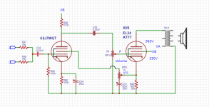
Ok it sounds like I need to redesign this to Cathode bias as in the attached. I have seen where some people have suggested increasing the value of R49 to 330k or 470k, but I am not sure why. (R50 should be 1.2K) (XA =360, XB=250 according to 5C1 schematic, I'm using the PS unchanged).
The reason given for the NFB used was to mimic what was done in the 5F1, but in that schematic the NFB comes off the OT back to the coupling cap at the 6V6 input. Would that be a better way to go?
This is the sound file for the amp built on the 1st schematic posted in #1
http://tube.ghr.fi/champnfbtest.ogg
It seems to work well. I like the effect of this control.
I though NFB decrease output impedance, but this NFB circuit increases it? Is this high output impedance going to be a problem and what can be done to reduce the issue if it is? This is a guitar amp so i'm not so sure it is really an issue since I am going for the "distortion pot" effect anyways. I know it's not really a gain pot but the effect is that sounds like it is given the sound file in the link. I could use the 8K tap rather than the 5K tap? Using a vintage CTS 12" guitar speaker?
Attachments
Last edited:
I have seen where some people have suggested increasing the value of R49 to 330k or 470k, but I am not sure why.
Increasing the resistor increases the stage gain, to a point where the tube starts to starve itself and sound bad. The value of the plate resistor, screen resistor, and cathode resistor all interact with each other. A combination that works well with one guitar, may not sound great with something different.
I have a little 4 tube amp that uses a similar setup for it's input stage. I added a mosfet bootstrap circuit to extract mega gain from a pentode, but the principle is the same as your circuit. I wound up putting three pots in the circuit, one for the cathode resistor, one for the screen resistor, and another for the plate resistor. I spent a couple days and 4 or 5 different guitars turning the pots until I found a happy medium. Then I measured each pot and put resistors in the board. I have been using that amp for about 3 years.
I am partial to EMGs and I usually go for a heavy metal distortion but in this case I'm going for the late 50's, early 60s meets Malcom Young sound so I have a guitar with a vintage Gretsch filtertron that I plan on using. Seems like you know these things inside and out so what say you?
I really like your idea of using pots to test out a good sound for the amp, thanks! Looks like this will be a breadboard experiment for a while.
When it come to the power supply the vintage schematic call for a 5Y3 with 16uf and 8uf caps, this is probably a bit saggy, but I think this is part of the sound I'm looking for?
Also I have been informed the modern plastic breadboard I have been using is a bad idea, they short out on HT. even though I have it on a variac. What can you say about that? Considering building a wood board version.
Last edited:
I wound up putting three pots in the circuit, one for the cathode resistor, one for the screen resistor, and another for the plate resistor. I spent a couple days and 4 or 5 different guitars turning the pots until I found a happy medium.
I did the same thing for a 6AU6-6AQ5 amp circuit years ago. I had a pentode-triode switch on the 6AU6. I twiddled till I got the best sound on each, obviously different values.It was fun but I never kept the amp together. So many circuits, so little time. I have used the breadboards but I leave an appropriate amount of rows between voltages, two empty rows for the highest voltage should be ok.
Last edited:
......I though NFB decrease output impedance...
If it senses output _voltage_, which is commonly done.
This one senses output _current_.
Figure the whole thing as "experiment", and leave room to change.
There are four different types of negative feedback....I though(t) NFB decrease output impedance...
As PRR said, the feedback can be taken either from output current, or output voltage. One raises output impedance, the other lowers it.
Additionally the feedback signal can be applied either in series with the input signal (ex. cathode follower), or in parallel to it (ex. inverting op-amp circuit). Series feedback raises input impedance, parallel feedback lowers it.
All together, this gives you four different possible combinations, and each of the four produces a different result. This allows a circuit designer to choose higher or lower input impedance, and also higher or lower output impedance, whatever suits the purpose best.
It's not often that we want low input impedance in guitar circuits, so parallel feedback is less frequently used, particularly in tube circuits, where it takes away one of the advantages tubes had over early-generation semiconductors.
-Gnobuddy
- Home
- Live Sound
- Instruments and Amps
- Champ 5C1 with equivalent tube options