Hi,
I’ve been working on an amplifier concept for several weeks now and I’m still struggling with the phase inverter.
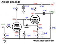
My input stage is from tubecad.com, aikido style with a 6SN7. With 0.71 VRMS (1 VPP) I get 10 VRMS output, with 1.42 VRMS (2 VPP) I get 20 VRMS output. Distortion is low, around 0.15 - 0.2%. B+ for input and phase splitter is 400 VDC regulated and stable).
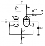
My second stage is also a 6SN7 (although I also tried an ECC83). I tried all sorts of configurations, Cathodyne, Long Tailed Pair and Schmitt (see attachment). I tried the LTP and Smitt (1) with a resistor to ground and (2) with a CCS (10M45S) to (a) ground and (b) -50 VDC.
My observations are quite frustrating:
1. With low phase splitter output (< 5 VRMS) distortion is around 0.5% or even lower
2. Distortion becomes easily above 1% and a lot more with higher output voltages (distortion measured after the output capacitor).
Output stage is 2 x KT150 PP, capacitor coupled. This stage adds approx. 0.15 to 0.2% distortion.
For driving the KT150 tubes for full output (50 Watts or slightly more) I will need more drive than I can get now without high distortion. I haven’t been able to measure exactly what is needed, but I guess it will be 25 VRMS or more.
I wonder if anyone has suggestions where to look or, what to try. For now it looks asif I have tried almost anything within my reach (2 x 6SN7 and 2 x KT150).
Regards, Gerrit
I’ve been working on an amplifier concept for several weeks now and I’m still struggling with the phase inverter.
My input stage is from tubecad.com, aikido style with a 6SN7. With 0.71 VRMS (1 VPP) I get 10 VRMS output, with 1.42 VRMS (2 VPP) I get 20 VRMS output. Distortion is low, around 0.15 - 0.2%. B+ for input and phase splitter is 400 VDC regulated and stable).
My second stage is also a 6SN7 (although I also tried an ECC83). I tried all sorts of configurations, Cathodyne, Long Tailed Pair and Schmitt (see attachment). I tried the LTP and Smitt (1) with a resistor to ground and (2) with a CCS (10M45S) to (a) ground and (b) -50 VDC.
My observations are quite frustrating:
1. With low phase splitter output (< 5 VRMS) distortion is around 0.5% or even lower
2. Distortion becomes easily above 1% and a lot more with higher output voltages (distortion measured after the output capacitor).
Output stage is 2 x KT150 PP, capacitor coupled. This stage adds approx. 0.15 to 0.2% distortion.
For driving the KT150 tubes for full output (50 Watts or slightly more) I will need more drive than I can get now without high distortion. I haven’t been able to measure exactly what is needed, but I guess it will be 25 VRMS or more.
I wonder if anyone has suggestions where to look or, what to try. For now it looks asif I have tried almost anything within my reach (2 x 6SN7 and 2 x KT150).
Regards, Gerrit
Attachments
Is that a problem? If distortion is 0.5% at 5Vrms, then you should expect 1% at 10Vrms, and 2% at 20Vrms...1. With low phase splitter output (< 5 VRMS) distortion is around 0.5% or even lower
2. Distortion becomes easily above 1% and a lot more with higher output voltages (distortion measured after the output capacitor).
Hi Merlinb,
Distortion looks to go almost exponential. With 6 VRMS it's already above 1%. With 10 VRMS it will be in the range of 10 - 15 %. I cannot tame the beast.
It just doesn't make sense to me why this is happening. For sure I'm not overloading my measuring device (Steinberg UR242).
In the literature it's hard to find adequate information about distortion and RMS output voltages. Lots of diagrams you can find, but can they generate 25 VRMS or more output?
Regards, Gerrit
Use a 12AX7/ECC83 in the differential gain block phase splitter. Good sized plate load resistors are needed to get stage gain up to roughly μ/4. Buffer the phase splitter triodes with DC coupled ZVN0545A source followers. The buffers keep splitter gain up and don't have problems with KT150 grid to ground resistance limits (they are low).
Hi Eli,
Do you have a diagram for this source follower? I need a capacitor between grid and splitter.
Regards, Gerrit
Do you have a diagram for this source follower? I need a capacitor between grid and splitter.
Regards, Gerrit
Sounds like you are clipping, which suggests you have an incorrect resistor value or wiring mistake or:Distortion looks to go almost exponential. With 6 VRMS it's already above 1%. With 10 VRMS it will be in the range of 10 - 15 %.
How are you connecting the tube stage to the UR242?...Steinberg UR242
Last edited:
Hi Eli,
Do you have a diagram for this source follower? I need a capacitor between grid and splitter.
Regards, Gerrit
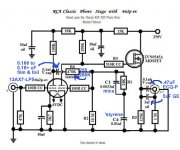
The provided tweaked RCA phono preamp shows the way. The FET is DC coupled to the driving triode and cap. coupled to the downstream load. Add a protective 12 V. Zener diode between gate and source to cope with power on transients.
Attachments
Merlinb: I use a 0.1uF capacitor with a 1MOhm resistor in series into a 100KOhm resistor. I measure the distortion using the voltage across the 100KOhm resistor. Voltages are measured with a true RMS DMM directly at the output capacitors of each stage. The UR242 is definitely not overloaded. I can see this on the spectrum analyser and the clipping indicator LED on the UR242 is far from indicating “ON”. Of course the phase splitter itself can be clipping (I think it does).
Eli D.: Your diagram is clear to me. I just ordered some MOSFET’s this afternoon. I will start testing with these early next week and post my findings here.
Regards, Gerrit
Eli D.: Your diagram is clear to me. I just ordered some MOSFET’s this afternoon. I will start testing with these early next week and post my findings here.
Regards, Gerrit
Hmm… maybe off color, but what about the Lundahl 1660S? Pretty impressive frequency response, delivers perfectly symmetric downwind secondary voltage, and never 'goes bad' once inserted into service. Y'know? ⋅-=≡ GoatGuy ✓ ≡=-⋅
Is the KT150 fixed bias and what resistors to the negative voltage are you using? I used a 6EJ7 pentode LTP circuit to drive 4x6550's but for lower gain there plenty of others (6BC6 etc).

Last edited:
Hi Baudoin0,
I’m using an autobias board from audioams.eu. Currently it’s set to 60 mA @ 600 VDC per tube. Connection of the negative voltage is with 100K series resistors.
I’m using an autobias board from audioams.eu. Currently it’s set to 60 mA @ 600 VDC per tube. Connection of the negative voltage is with 100K series resistors.
Merlinb: I use a 0.1uF capacitor with a 1MOhm resistor in series into a 100KOhm resistor.
Hmm, so the UR242 sees a source impedance of 100k, which is a lot. Try changing the 100k to 10k and repeating the tests.
Could you post the complete circuit as I think it may be causing a little confusion. Don't connect the UR242 directly to the output of the driver (through the coupling caps). The impedance will load the driver too much and cause much distortion. If you want to see what the driver is doing connect 100k from coupling cap and 2k2 to ground and take measurement there.
Cheers.
Cheers.
Last edited:
Baudoin0: The UR242 is not the problem, I don't have a direct connection with output. Right now it's 820Kohm into a 10KOhm resistor.
I don't have a complete or final diagram, since I'm experimenting with values and circuits on and on. I'm looking for the right diagram...
Mona: I have your phase splitter circuit connected now as second stage after the Aikido stage. When measuring it strikes me that there is such a big difference in VRMS on each anode. For example when the anode of the driven triode measures 20 VRMS, the anode of the second triode only reaches about 3 VRMS. In other words, they are far from balanced even though they share cathodes. Distortion is still huge compared to the driving stage.
Replacing tubes makes no difference (various 6SN7's, ECC83).
I will continue testing tomorrow...
Regards, Gerrit
Ok if you post your preferred driver schematic I can stick it on LTspice and have a look at the distorsion. That way you won't go through numerous board iterations. You have a negative rail. Your driving a KT150 and 100k resistor. What valves do you have available for the driver? Usually the best thing is to have a CCS in the cathode. That way the DC voltages are determined by the CCS and not the valve (assuming both halves are the same) and the AC balanced is guaranteed. The LTP gives you the highest drive.
Last edited:
Baudoin0, see post 1 for the Aikido stage and Mona’s post 11 for the phase splitter.
I would like to get this working. Tubes are 6SN7.
Regards, Gerrit
I would like to get this working. Tubes are 6SN7.
Regards, Gerrit
Mona: I have your phase splitter circuit connected now as second stage after the Aikido stage. When measuring it strikes me that there is such a big difference in VRMS on each anode. For example when the anode of the driven triode measures 20 VRMS, the anode of the second triode only reaches about 3 VRMS. In other words, they are far from balanced even though they share cathodes. Distortion is still huge compared to the driving stage.
Replacing tubes makes no difference (various 6SN7's, ECC83).
Well at the risk of tickling everyone's sense of the obvious … are the anode resistors REALLY the same Ω value? Here's the quick check … measure them with the amplifier cold, and unpowered. They can be measured as if they are isolated. Might ask the same about the pair of 470 kΩ mutual high-bias resistors, too.
In a nutshell (since you did change the valves, eliminating that as the source of the asymmetry), the asymmetric VRMS measurements are an indication of either substantially different loads for each triode, or some other circuit connection 'problem'.
IF a pair of triodes, with a near-fixed current source in the cathode, shared by both is in place, as long as the loads on the cathodes are also well matched (and there's nothing defective about the dual-triode valve!), then almost perfect signal reflection symmetry will take place.
With one big caveat: that the signal coming into the so-called phase splitter does not get very close to the quiescent bias point of the lashed-together cathodes, in peak. If the signal overshoots the bias point, then that triode will be driven into positive-grid conduction. As soon as that happens, all guarantees of signal symmetry are thrown out the window.
⋅-⋅-⋅ Just saying, ⋅-⋅-⋅
⋅-=≡ GoatGuy ✓ ≡=-⋅
- Home
- Amplifiers
- Tubes / Valves
- Challenge with Phase Splitter