Hi,
So far I've build a few supplies, where I used lm317 for regulation. Unfortunately, I don't have any equipment to actually see the DC current, so I'm just guessing the outcome.
I'm using a resistor between reservoir and filter capacitors. I've found a formula 1/2PiRC - I either have to limit the current output, or to put a large capacitor bank to get under 1 Hz.
My questions are: would multiple 6800uF caps overstress the diodes/transformer; would I get the same result by using two R/2 resistors with two 3300uF smoothing capacitors? I don't have experience with using choke instead of the resistor.
Any other ways to improve the DC output?
Last edited:

If you are asking about the equipment, I'd recommend you start an assistance thread since it is specialised work and involves high voltages.
If you meant PSUDII, here is a link - https://www.diyaudio.com/community/threads/psud-2-10-released.345649/ 🙂
If you meant PSUDII, here is a link - https://www.diyaudio.com/community/threads/psud-2-10-released.345649/ 🙂
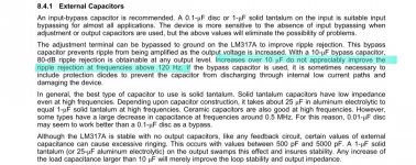
Here's a cutout from Texas instruments paper concerning Lm317/337.
I'm looking for an recommendation regarding capacitor usage, since tantalums are rather pricy. Paper states tantalum electrolytes have a clear advantage over traditional aluminums.
However, since this is a linear power supply, with a conventional transformer (with electrostatic shield between windings), with no switching elements, do we have any high frequency noise at all? Would a tantalum cap in place of adjustment and output caps be just a waste of money?
On the other hand, if linear PSUs exhibit noise of around 120Hz, could significantly larger adjustment cap do anything to improve upon that?
Thanks in advance.
Attachments
Last edited:
Modern E-caps, including the cheapest Multicomp ones are almost flawless. Don't overthink/overdesign. Solid polymer caps are superior in almost all respects, but their near-ideality makes them dangerous in novices hands. You can easily create unwanted resonances if you don't know exactly what you are doing.
Simply use standard, modern E-caps, and don't over-bypass the output, as it can have negative effects. If you want better performance on the cheap, use a denoiser, but use it carefully, keeping in mind all the requirements and caveats when using a (relatively) high performance circuit
Simply use standard, modern E-caps, and don't over-bypass the output, as it can have negative effects. If you want better performance on the cheap, use a denoiser, but use it carefully, keeping in mind all the requirements and caveats when using a (relatively) high performance circuit
Post the exact schematic, and the circuits powered by it.I'm using a resistor between reservoir and filter capacitors. I've found a formula 1/2PiRC - I either have to limit the current output, or to put a large capacitor bank to get under 1 Hz.
Sorry for short absence.
I've looked into PSUD2, it shows voltage after first RC filter to be identical to the voltage after second RC - very flat.
I've made a simple design using solid electrolytic caps (as per Lm317 brochure from TI)
https://www.vishay.com/docs/40020/199d.pdf
I've put 1uF solid electro. cap on ADJ terminal to ground and another one as an output bypass (in combination with another MLC cap 0,1uF as an output bypass). It's not mine shematics design - 10uF electolytic caps were used originaly insted of those 1uF tantal I put.
I've looked into PSUD2, it shows voltage after first RC filter to be identical to the voltage after second RC - very flat.
Can you please elaborate "modern E caps" term - conventional ones or solid elec. or something third?Modern E-caps, including the cheapest Multicomp ones are almost flawless. Don't overthink/overdesign. Solid polymer caps are superior in almost all respects, but their near-ideality makes them dangerous in novices hands. You can easily create unwanted resonances if you don't know exactly what you are doing.
Simply use standard, modern E-caps, and don't over-bypass the output, as it can have negative effects. If you want better performance on the cheap, use a denoiser, but use it carefully, keeping in mind all the requirements and caveats when using a (relatively) high performance circuit
I've made a simple design using solid electrolytic caps (as per Lm317 brochure from TI)
https://www.vishay.com/docs/40020/199d.pdf
I've put 1uF solid electro. cap on ADJ terminal to ground and another one as an output bypass (in combination with another MLC cap 0,1uF as an output bypass). It's not mine shematics design - 10uF electolytic caps were used originaly insted of those 1uF tantal I put.
I'm making multiple PSUs, one for supplying preamp, one for op amps of active crossover and third one for spdif converter.Post the exact schematic, and the circuits powered by it.
As for the preliminary schematics:
Filter section, resistors around 20ohms, and capacitors in 2200-3300uF range.
Regulator section (10uF electrolytes originally in place of 1uF tantals)
A useful starting point for your PSUD studies, might be
CIN (capacitance at input pin of regulator) = 10,000 microfarads per ampere of max possible load current = 10 microfarads per milliamp of max possible load current
and also
COUT (capacitance at output pin of regulator) = whichever is greater, (A) 33 micforarads; or else (B) { CIN/50 }
For newbies I recommend you only use Panasonic or Nichicon electrolytic capacitors with LM317/LM337 regulators, and you only buy them from trusted distributors such as Farnell, Jaycar, Element14, Mouser, DigiKey, etc.
what happens if you exceed that capacitance value?A useful starting point for your PSUD studies, might be
CIN (capacitance at input pin of regulator) = 10,000 microfarads per ampere of max possible load current = 10 microfarads per milliamp of max possible load current
and also
COUT (capacitance at output pin of regulator) = whichever is greater, (A) 33 micforarads; or else (B) { CIN/50 }
For newbies I recommend you only use Panasonic or Nichicon electrolytic capacitors with LM317/LM337 regulators, and you only buy them from trusted distributors such as Farnell, Jaycar, Element14, Mouser, DigiKey, etc.
if we assume that there are two capacitors before the regulator - one just after the rectifier and another one within RC filter - would CIN be the sum of the two, or just the value of the first one?
maybe a better question - if 1n400x diodes are used - would 3 capacitors rated at 3300uF exceed diodes' maximum current rating while charging?
I mean ordinary, wet Al E-caps, just ordinary stuff. If you use ultra-high perf caps in the wrong places, you are going to create resonances and noise peaks if you do not exactly know what you are doing.Can you please elaborate "modern E caps" term - conventional ones or solid elec. or something third?
Also, be aware that the practice of adding a random 100nF cap across a larger one is generally detrimental, unless you keep the cap ratio well below 100, and you use the right technologies.
Otherwise, refrain from it
- Home
- Amplifiers
- Power Supplies
- Chaining filters