There are many ways to stabilize CFPs.
First it helps to understand what a CFP is and how it works.
The best explanation, that helped me a lot, is what I found here: https://electronics.stackexchange.com/a/474070
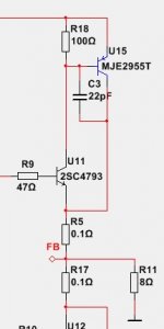
When I suspected I might have an unstable CFP, I simulated this. Put a Tian probe at the feedback input (U11 emitter in your schematic) and observe the gain and phase margins. I did not find capacitors very helpful, but had better success with ferrites at the feedback node. This preserves high performance at lower frequency and improves stability. Do your own simulation to find out what works best with your specific application and components used.
First it helps to understand what a CFP is and how it works.
The best explanation, that helped me a lot, is what I found here: https://electronics.stackexchange.com/a/474070
When I suspected I might have an unstable CFP, I simulated this. Put a Tian probe at the feedback input (U11 emitter in your schematic) and observe the gain and phase margins. I did not find capacitors very helpful, but had better success with ferrites at the feedback node. This preserves high performance at lower frequency and improves stability. Do your own simulation to find out what works best with your specific application and components used.
Simulations aside, on a practical CFP circuit, oscillation is effectively suppressed adding a small resistor at the U11 emitter. CFP made with BD139/MJL1302, on a breadboard with long wires and enough parasitic inductances to oscillate, is made stable by using 10 Ω at the BD139 emitter, without any additional capacitor.
Of course, that means internal CFP feedback is reduced and amplifier distortion will be higher, but results are still outstanding.
If additional capacitor is still required, than single capacitor at the BC pins of first transistor in the “PNP CFP” is enough, like here: Rod Ellott amplifier
Of course, that means internal CFP feedback is reduced and amplifier distortion will be higher, but results are still outstanding.
If additional capacitor is still required, than single capacitor at the BC pins of first transistor in the “PNP CFP” is enough, like here: Rod Ellott amplifier

The resistor in emitter is a good advice. I will try this.
Another thing. Even if amplifier is stable in simulation it might be oscillating in real life.
Another thing. Even if amplifier is stable in simulation it might be oscillating in real life.
The Tian probe is one of the options to simulate loopgain / stability margins. Small signal simulation is helpful, but large signal behavior is different. Simulation is only as precise as the models and the simulation setup. Not including any parasitic elements like wiring inductance is somewhat pointless.
Putting a resistor in the U11 emitter works, but ruins performance all over the place. Better is to put a frequency dependent resistor here, i.e. a suitable ferrite, which improves HF stability without ruining performance.
Since CFPs are just simple CFAs, it becomes clear why they are brilliant for small signal applications where they operate in class A and CFPs are a bad idea for power output stages operated in class AB, where the tiny amplifier is switched on and off with each half wave. While the class AB operated CFA still yields lower THD while it is on, it has inherently high crossover distortion.
LTspice contains an example that shows how to use a Tian probe. It can be found in the "examples\Educational" folder with the filename LoopGain2.asc.
Better is to put a frequency dependent resistor here, i.e. a suitable ferrite, which improves HF stability without ruining performance.
Can you share practical advice/experience on suitable ferrite beads/inductors?
Here is my research I did a while ago with a CFP used as capacitance multiplier (see Keantoken's kmultiplier).
I was not using the recommended transistors, experienced issues and tried to narrow down the root cause.
This is the loopgain plot of the uncompensated CFP:

Phase margin is ~35° and gain margin is ~14dB, which is healthy for such a small loop in my opinion.
Nonetheless I wanted to figure out how to improve this just as a learning experience since I just read that the CFP is actually a small CFA.
This is how loopgain looks like with 33pF connected between base and collector of the small signal transistor:

Phase margin is ~27° and gain margin still ~13dB.
The same capacitor put base to collector at the power transistor:

Phase margin at ~26° and gain margin ~13dB.
Not an improvement at all. Maybe a bigger capacitor would have better effect? I don't know.
Putting a 10 Ohm resistor in series with the emitter of the small signal transistor ruins OLG in the lower frequency range from previously almost 30dB to ~21dB:

Phase margin is 60° now and gain margin better than 15dB. The resistor is very effective stabilizing the CFP.
Obviously 10 Ohm is too much. This also shows how much performance and stability depends on the specific transistors re.
This is my attempt to use a ferrite in series with the small signal transistors emitter:

Performance below 1MHz is till good and phase margin of ~36dB and more than plenty of gain margin look very stable.
For the simulation I selected a multi-layer chip ferrite, but in reality I put a small ferrite core over the transistors leg as safety precaution against oscillation.
Selecting ferrites is a bit difficult. I'm not a specialist on this and the best ferrite depends on the specific application.
You may also want to experiment with ferrites that have a resistor in parallel. I find this very useful for (further) lowering Q of the ferrites.
With different transistors the simulation would look different for sure and you might come to different conclusions.
I can only encourage to do some simulation on your own.
Please share your results.
I would love to know whether my theory and findings make sense or not.
I was not using the recommended transistors, experienced issues and tried to narrow down the root cause.
This is the loopgain plot of the uncompensated CFP:
Phase margin is ~35° and gain margin is ~14dB, which is healthy for such a small loop in my opinion.
Nonetheless I wanted to figure out how to improve this just as a learning experience since I just read that the CFP is actually a small CFA.
This is how loopgain looks like with 33pF connected between base and collector of the small signal transistor:
Phase margin is ~27° and gain margin still ~13dB.
The same capacitor put base to collector at the power transistor:
Phase margin at ~26° and gain margin ~13dB.
Not an improvement at all. Maybe a bigger capacitor would have better effect? I don't know.
Putting a 10 Ohm resistor in series with the emitter of the small signal transistor ruins OLG in the lower frequency range from previously almost 30dB to ~21dB:
Phase margin is 60° now and gain margin better than 15dB. The resistor is very effective stabilizing the CFP.
Obviously 10 Ohm is too much. This also shows how much performance and stability depends on the specific transistors re.
This is my attempt to use a ferrite in series with the small signal transistors emitter:
Performance below 1MHz is till good and phase margin of ~36dB and more than plenty of gain margin look very stable.
For the simulation I selected a multi-layer chip ferrite, but in reality I put a small ferrite core over the transistors leg as safety precaution against oscillation.
Selecting ferrites is a bit difficult. I'm not a specialist on this and the best ferrite depends on the specific application.
You may also want to experiment with ferrites that have a resistor in parallel. I find this very useful for (further) lowering Q of the ferrites.
With different transistors the simulation would look different for sure and you might come to different conclusions.
I can only encourage to do some simulation on your own.
Please share your results.
I would love to know whether my theory and findings make sense or not.
Thank you for the detailed info.Here is my research I did a while ago with a CFP used as capacitance multiplier (see Keantoken's kmultiplier).
I was not using the recommended transistors, experienced issues and tried to narrow down the root cause.
IME, 33 pF is too small value to have any real effect. Typically, using 330 – 470 pF makes CFP stable.This is how loopgain looks like with 33pF connected between base and collector of the small signal transistor:
Phase margin is ~27° and gain margin still ~13dB.
Not an improvement at all. Maybe a bigger capacitor would have better effect? I don't know.
Yes, 10 Ω is too much in ideal case. However, that is enough for a CFP output amplifier stage to remain stable, with a capacitive load (tested up to 1 uF). Distortion of simple diamond buffer output stage, working in class A, was still excellent with distortion around 0.001% at 1W/8Ω.Putting a 10 Ohm resistor in series with the emitter of the small signal transistor ruins OLG in the lower frequency range from previously almost 30dB to ~21dB:
Phase margin is 60° now and gain margin better than 15dB. The resistor is very effective stabilizing the CFP.
Obviously 10 Ohm is too much. This also shows how much performance and stability depends on the specific transistors re.
https://www.diyaudio.com/community/threads/output-bjts-for-buffer.386324/post-7033808
Your findings are very helpful. Thanks’ again. I’ll test stability with RF ferrite coils I have at hand.With different transistors the simulation would look different for sure and you might come to different conclusions.
I can only encourage to do some simulation on your own.
Please share your results.
I would love to know whether my theory and findings make sense or not.
Thanks! That's one of my posts over there lolFirst it helps to understand what a CFP is and how it works.
The best explanation, that helped me a lot, is what I found here: https://electronics.stackexchange.com/a/474070
CFP works well with capacitive loads (as in regulators) but the cap needs some ESR for stability, a MLCC or film cap would be a bad idea... and careful simulation using circuit parasitics... CFP's output impedance should meet the cap's impedance at a 45° angle on the impedance plot.
CFP impedance in red, cap impedance in green, whole thing in blue, MMBT3904/BD140:
Bigger electrolytic cap, still OK
Cap too small, not OK
Of course the flat part of the CFP output impedance depends on gm of driver transistor, so Zout decreases at high current, loop gain increases, so it's important to sim it over the whole current range...
If the transistors are slow then the cap needs to be bigger to intercept CFP Zout before it begins to rise.
I had problems when using CFPs as drivers because the base of the power transistor they're driving is a capacitor and its value is variable, plus it sweeps through a wide range of CFP output current, it'll find the "sweet spot" to throw a burst of oscillation when it feels like it...
You're right, 33pF is not enough.IME, 33 pF is too small value to have any real effect. Typically, using 330 – 470 pF makes CFP stable.
[...]
I’ll test stability with RF ferrite coils I have at hand.
I ran simulation again with 330pF and found out that higher capacitance improves gain margin a lot, but at the cost of decreasing phase margin. While this approach does not work well in my application, capacitors could work well in other CFP applications. There must be a reason this technique is used for stabilization of CFPs.
I also ran simulation with a different ferrite. Previous one was 782763480 from Würth. The 782422221 has more impedance and works even better.
The ferrite I actually installed is the 74270001 from Würth. This one is perfect for putting over a TO-92 transistor leg and the impedance is rather on the high side. Like shown in my plots earlier, ferrites seem to help with gain margin only, but don't worsen phase margin, which is a partial success at least.
I attached the LTSpice file for playing around on your own if you like. Be warned my simulation setup is a terrible mess.
Attachments
Thanks again for the great explanation! 👍Thanks! That's one of my posts over there lol
CFP works well with capacitive loads (as in regulators) but the cap needs some ESR for stability
OMG, you are absolutely right: The capacitor at the output has far more impact on stability than anything else in my capacitance multiplier.
Lucky I have a high ESR cap there, but I also have some small film caps for local decoupling. The small caps degrade stability and this is getting worse with closer proximity to the capacitance multiplier and better with more inductance in between (i.e. further away).
This leads to another idea for stabilization: Put a ferrite or inductor with a resistor in parallel where you have the CFPo resistor in your schematics. Just like at any amplifier output. Seems to work well and should allow low ESR caps at the output.
YesThe capacitor at the output has far more impact on stability than anything else
For a low-ESR cap the value has to be high enough and the layout has to be tight with a ground plane. Without a ground plane the cap will have a lot more inductance, and if it has low ESR, that makes a ringing LC circuit. Also if the cap has high inductance it won't be able to dominate the output impedance at HF. So it works well with 1-10µF MLCC on a ground plane. But on oldskool single layer layouts, different story. 4 layer is so cheap these days, that's not a problem anymore.
Here's a high inductance example: the inductance on Q1's base wrecks it. Note output current is stepped. Here the cap's ESR is quite high so it is useless. The CFP would be unstable without the cap simply due to the inductance in Q1's base...
Basically if Q1's reference has high inductance it needs some positive real impedance (resistance) in series.
Last edited:
Thanks a lot! The small caps really create a mess.
I thought I would be safe putting low ESR film caps in parallel with high ESR electrolytic caps so they don't resonate with each other, which is true, but still the low ESR creates trouble with the capacitance multipliers, which is sad.
Enough thread-jacking now with my capacitance multiplier.
I guess lineup wanted to discuss about CFPs in amplifier output stages.
I put together a CFP this way and wanted to see whether my theory also applies here.
Standing current in the power transistors is 65mA and 12mA in the drivers - just an arbitrary choice.
There is plenty of phase margin, no worries, but there is also a gain peak just when the phase hits 180°.
I could not tame the gain peak with the capacitors, but the ferrites work well here, too.
A too strong ferrite yields no further improvement, but worsens phase margin instead.
I tried with what I had at hand, large 30 mm diameter ferrite rings. It was enough to pass straight wire, going from emitter of first CFP BJT, through ferrite ring and CFP is perfectly stable, with no additional capacitors or emitter resistors, even with excessive capacitive load. Test was made with the same diamond buffer as mentioned at post #10.
I think I’ll go with combination of small emitter resistor and ferrite bead directly at BD139/BD140 leg.
So, it’s confirmed – ferrite beads are great way to make CFP stable. 👍
I think I’ll go with combination of small emitter resistor and ferrite bead directly at BD139/BD140 leg.
So, it’s confirmed – ferrite beads are great way to make CFP stable. 👍
depends on what causes the output stage to become unstable.Is this the correct way to add a capacitor for stability?
instability can be caused by the use of an audiophile speaker cable that has low inductance but high capacitance, it will be necessary to correct such a wire not only at the output of the amplifier but also at the end of such a cable at the speaker terminals.
The inductance bead in the base of the Shiklai output assembly transistor - in my opinion, this is an attempt to cover the correction associated with the load with a feedback circuit, but you can also cover the inductor at the amplifier output with negative feedback, then it turns out the same as the inductor bead in the base of the transistor, only with greater efficiency - maybe.
A CFP can go unstable just on its own without any load as shown.depends on what causes the output stage to become unstable.
instability can be caused by the use of an audiophile speaker cable that has low inductance but high capacitance, it will be necessary to correct such a wire not only at the output of the amplifier but also at the end of such a cable at the speaker terminals.
The inductance bead in the base of the Shiklai output assembly transistor - in my opinion, this is an attempt to cover the correction associated with the load with a feedback circuit, but you can also cover the inductor at the amplifier output with negative feedback, then it turns out the same as the inductor bead in the base of the transistor, only with greater efficiency - maybe.
And some capacitive loads also may also contribute to instability.
Esoteric amplifiers that omit the output inductor together with esoteric cables like you mention will likely be unstable. There have been exhaustive discussions about output inductors already.
Any well designed amplifier has the usual output network: A snubber at the NFB node to ground and a series inductor with resistor in parallel to isolate capacitive loads from the amplifier. Another snubber after the output inductor probably can help with esoteric cables.
The mechanism is different:
The ferrite in the CFP drivers emitter compensates the loopgain of the CPF, while the inductor at the CFP or amplifier output isolates the load capacitance.
The idea to add the ferrite in series with the CFP driver transistors emitter stems from the insight that the CFP is actually a CFA. And stability of a CFA depends on the resistor going to the inverting input. The higher the resistor, the more stable, but also the slower is the CFA. This is why CFAs usually have a rather low value, but high power rating resistor in the feedback network.
Ferrites are a bit obscure and I somehow doubt the way they are modeled, which is basically an inductor with a resistor in parallel. In reality this is an inductor mostly, but a lossy one, thus the resistive part. The inductive portion of the ferrite could well cause issues. Mitigation of the ferrites inductance can be a discrete resistor in parallel to dampen resonance with capacitors, just like it is commonly done with the amplifier output inductor.
Thanks again to tombo56 who confirmed that the compensation using a ferrite works in reality.
Also the combination of a low value resistor with a ferrite in series may be a good idea as belt an braces approach.
I agree, and I personally think that a ferrite bead on the base circuit will not work well without additional resistance in the emitter of the same transistor, because. the firrite bead only limits the frequency spectrum at the input, and the resistor in the emitter further reduces the gain.Thanks again to tombo56 who confirmed that the compensation using a ferrite works in reality.
Also the combination of a low value resistor with a ferrite in series may be a good idea as belt an braces approach.
I'm still struggling with my capacitance multiplier.
While I was clever enough to put a high ESR electrolytic as output capacitor for the capacitance multiplier, I also have several small film caps along the daisy chain power supply routing, which meanders to the places on the PCB where supply voltage is needed. Thus, the routing is rather long and local decoupling seems to make sense. But the small caps turn the previously nice gain phase plot into a wild roller coaster. Right now I have 100nF caps installed and it seems this is a bad idea and previous simulation by Peufeu illustrated that nicely.
This is how it looks like with some 100nF caps:

Clearly unstable due to zero phase margin.
I could install 470nF film caps instead and this looks a bit better:

470nF is the largest film cap I could put in those locations. Peufeu is right: The bigger the cap, the better.
A pretty good solution to make the capacitance multiplier unconditionally stable is the one discussed previously: Adding a series inductor to the output and lower Q with a parallel resistor. Like this (note I removed the short circuit across the ferrite with 3R3 in parallel to enable the filter network):

Unfortunately there is no way to implement this on the PCBs I have, which are the third revision already and I'm not willing to do a fourth revision.
I guess I'm going to change all 100nF caps to 470nF - while not ideal it is better than what I have now.
What is your opinion?
While I was clever enough to put a high ESR electrolytic as output capacitor for the capacitance multiplier, I also have several small film caps along the daisy chain power supply routing, which meanders to the places on the PCB where supply voltage is needed. Thus, the routing is rather long and local decoupling seems to make sense. But the small caps turn the previously nice gain phase plot into a wild roller coaster. Right now I have 100nF caps installed and it seems this is a bad idea and previous simulation by Peufeu illustrated that nicely.
This is how it looks like with some 100nF caps:
Clearly unstable due to zero phase margin.
I could install 470nF film caps instead and this looks a bit better:
470nF is the largest film cap I could put in those locations. Peufeu is right: The bigger the cap, the better.
A pretty good solution to make the capacitance multiplier unconditionally stable is the one discussed previously: Adding a series inductor to the output and lower Q with a parallel resistor. Like this (note I removed the short circuit across the ferrite with 3R3 in parallel to enable the filter network):
Unfortunately there is no way to implement this on the PCBs I have, which are the third revision already and I'm not willing to do a fourth revision.
I guess I'm going to change all 100nF caps to 470nF - while not ideal it is better than what I have now.
What is your opinion?
- Home
- Amplifiers
- Solid State
- CFP Complementary Feedback Pair - when and how to compensate for stability?