On your second point, I think it's been called a VFA I believe because both the + and the - inputs are high z inputs.
Correct, the exact analogy being that the input voltage appears accross the resistor generating current that is mirrored into a high impedance node.
DIYaudio semantic revolution 😉
That's why I said it's probably best not to discuss it. There will be no agreement.
😉
With the IPS I have some experimenting. Here, for example, is a nice simple solution. However, I can not estimate how well the PSRR is.
Something like this was applied by Marantz in the big Reference amplifiers.
Sajti
I simmed it - the gain/ frequency behavior is similar to a CFA and the peak current into the TIS is not limited by a current source as in a VFA. In my book this makes it a CFA.
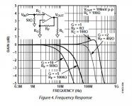
We have some confusion here. This is AD8055 very early H-bridge op-amp, almost nothing more than PMA's schematic. 1400V/us. BW does the VFA thing, a little peaking falsely extends 0dB number just a little.
Attachments
Last edited:
Something like this was applied by Marantz in the big Reference amplifiers.
Sajti
Krell does likewise.
Simple?!!?With the IPS I have some experimenting. Here, for example, is a nice simple solution. However, I can not estimate how well the PSRR is.
But I'm not sure your DC currents and operating points are stable. 😕
Simple is 10 active devices (IPS).
"embellished" is 14-16 devices.
More than this , nobody will build it. 🙄
PS - that is my attraction to CFA , I can give PPM with <14 semi's !
Edit - or even 8 ... VSSA with hawksford -32 ppm 4R 120 V p-p
OS
"embellished" is 14-16 devices.
More than this , nobody will build it. 🙄
PS - that is my attraction to CFA , I can give PPM with <14 semi's !
Edit - or even 8 ... VSSA with hawksford -32 ppm 4R 120 V p-p
OS
Last edited:
We have some confusion here. This is AD8055 very early H-bridge op-amp, almost nothing more than PMA's schematic. 1400V/us. BW does the VFA thing, a little peaking falsely extends 0dB number just a little.
Thanks for posting this up.
I've just redone my sims. For gain stepped from 10dB through 31.5 dB the -3dB CLG moves from ~575 kHz to 350 kHz with the ~575 kHz remaining essentially constant from 10 dB through 25 dB CLG which I would equate with the gain sweet spot often referred to in CFA application notes. This is with the bridge tie resistor set to 100 Ohms.
With the tie resistor set to 10 Ohms the -3 dB CLG drops from 575 kHz to 520 kHz over the same range. I would conclude that the BW is independent of the gain with these results.
If I MC the amp, then I get classic VFA behavior. At the low gain range end the -3 dB is at 530 kHz while at 31 dB CLG the -3 dB BW is 155 kHz
It was the results above that lead me to categorize the H input as CFA.
I will put my plots up later today (I printed them out and manualy marked the -3dB intercept points up - the photos are somewhere in the cloud waiting to drop into my mail box . . . )
Last edited:
Come on OS he only has about 20 transistors in the input section!
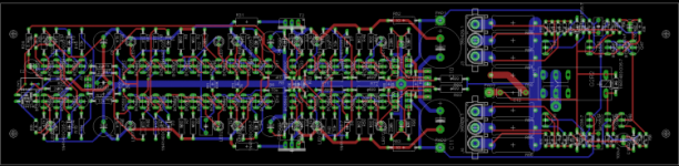
Input stage with 50 transistors. 1ppm 20kHz 8ohm 120W.
Sajti
Attachments
sajti,
I think my Hungarian ancestors would say Jeez, don't you think that is a bit excessive! Most people want a minimum of devices and the general feeling seems to be less devices sound better even if you can get to virtually zero ppm distortion with that many devices.
I think my Hungarian ancestors would say Jeez, don't you think that is a bit excessive! Most people want a minimum of devices and the general feeling seems to be less devices sound better even if you can get to virtually zero ppm distortion with that many devices.
sajti,
I think my Hungarian ancestors would say Jeez, don't you think that is a bit excessive! Most people want a minimum of devices and the general feeling seems to be less devices sound better even if you can get to virtually zero ppm distortion with that many devices.
Yeah, it's a bit overkill, but most of the transisitors are BC550C/560C, so they are quite cheap. This driver stage contains 2 individually feedbacked amplifier, to reduce the back EMF. This is not my idea, as Marantz use same amount of devices in their Reference series.
Sajti
If the design is good and self-balancing and it makes sense for the sound quality, I personally don't care how many transistors it takes... 20, 30 50... especially if they are BC550C/560C )
If the design is good and self-balancing and it makes sense for the sound quality, I personally don't care how many transistors it takes... 20, 30 50... especially if they are BC550C/560C )

Presumably, the THD20k @ 100W are SPICE world numbers.safti said:Input stage with 50 transistors. 1ppm 20kHz 8ohm 120W.
Would you like to post the ASC so we can be astounded and amazed and maybe learn something? 🙂
Last edited:
Presumably, the THD20k @ 100W are SPICE world numbers.
Would you like to post the ASC so we can be astounded and amazed and maybe learn something? 🙂
Will do that, but only evening, as it is on my home PC.
Sajti
Last edited:
Presumably, the THD20k @ 100W are SPICE world numbers.
Would you like to post the ASC so we can be astounded and amazed and maybe learn something? 🙂
yes, would be very interesting for me as well

sajti,
I think my Hungarian ancestors would say Jeez, don't you think that is a bit excessive! Most people want a minimum of devices and the general feeling seems to be less devices sound better even if you can get to virtually zero ppm distortion with that many devices.
Then , there is the support-troubleshooting factor. With 10-14 devices ,
only a few test points to go through when a builder has a problem or
gets something wrong.
30-50 may be good for a commercial module or something that can
be reworked at the factory .... but not DIY ?
This is the "attraction factor" for the Pass designs.
OS
OS,
I think of the First Watt as a way to learn the basic concepts of an amplifier circuit. Not sure that many of us could get away with such a low powered amplifier with the speakers we have.
I think of the First Watt as a way to learn the basic concepts of an amplifier circuit. Not sure that many of us could get away with such a low powered amplifier with the speakers we have.
Input stage with 50 transistors. 1ppm 20kHz 8ohm 120W.
Sajti
Hello Sajti,
Could you post a photo of your amp mentioned here if you have one.
Regards
Arthur
- Home
- Amplifiers
- Solid State
- CFA Topology Audio Amplifiers