We already know that. He thinks it's a VFA. Does his opinion make it so 😀?
It's indeed funny to note how some contributors around are staunch supporters of CFA's, without even being able to understand and identify one as so.
Well he is correct.
Its even funnier how some other contributors that are supposed to have some credentials to identify between CFA and VFA are not able to do so.
If you can change the ULGF by changing the feedback resistor does this mean you are dealing with a CFA?
Yep.
Well he is correct.
Its even funnier how some other contributors that are supposed to have some credentials to identify between CFA and VFA are not able to do so.
Well, Mr. Curls now changed his opinion. So your comment applies to him as well? Mine remains valid
.I would have thought youd stick to a CFA type here too.
Nevertheless it probably uses njm2068 opamps which are not to bad either, that is sound wise. Others will smirk that this opamp is used even in their 5000 $ + amps.
Its only used as an input X1 buffer to drive a LP filter and then to the IPS of the amplifier - which is CFA. So, it did not matter much... I wanted some of the specs of the LT for the input. Like higher SR. Even higher could be used.... because it is accepting anything and everything coming in on the cable which may be other than the intended audio and I dont want a low SR opamp to mishandle/distortion its output going into the LP filter.
BTW - I found that LT opamp to be conservatively rated and exceeds by a wide margin, its original 16 bit app. I use it in HP339A as a replacement for older opamps and produces extremely low distortion.
Thx-RNMarsh
Last edited:
We already know that. He thinks it's a VFA. Does his opinion make it so 😀?
./QUOTE]
I think JC's compl diff IPS is, of course, VFA. JC said he tried CFA in the early days and didnt work well for him at that time.
One characteristic of the 'Classic' CFA topology (meaning - as patented and further developed by the IC industry) is its gain properties at low to moderate gains... that constant BW with gain change. It is a feature that could be useful in classifying the topology in question. That is, does the gain-BW behavior look like a CFA or VFA?
THx-RNMarsh
Last edited:
If you can change the ULGF by changing the feedback resistor does this mean you are dealing with a CFA?
I don't think this is quite true, since you can change ULGF by changing the feedback resistor in either a CFA or VFA. In an amp with a closed loop gain of 20, cutting only the FB resistor in half will about double ULGF in either topology.
However, if you cut both the feedback resistor and the feedback shunt resistor, then the ULGF of the VFA will remain about the same, while the ULGF will increase for the CFA.
So, halving the impedance of the complete FB network, will change ULGF with a CFA, while it will not for a VFA (to first order).
Here's a question. Consider the classical RIAA preamp, where feedback is taken from the output to the emitter of the first stage. Passive components in the series part of the feedback path change the gain as a function of frequency to implement the RIAA EQ. The emitter shunt resistor is fixed.
Is this a CFA? I think it is, at least when the first transistor is biased with enough current that its gm makes the impedance seen at its emitter small compared to the feedback network impedance. In this case, most of the feedback current flows into the emitter, rather than into the shunt resistor.
Cheers,
Bob
Well, which is it?
Hi John,
Nice circuit. I think it can be either considered VFA or CFA, depending on the various resistor and 1/gm ratios. It works pretty much just as well, whether it is closer to the VFA end of the behavior spectrum or the CFA end of the spectrum.
If most of the feedback current flows into the sources, it is more like a CFA. If most of the feedback current flows into the differential shunt resistance, then it is more like a VFA.
The closed loop gain will obey pretty much the same formula in either mode of operation, but the loop gain and ULGF will be affected differently in the two modes of operation.
Cheers,
Bob
See #5127, above. If you can answer that then you know which it is behaving like. .
THx-RNmarsh
THx-RNmarsh
I don't think this is quite true, since you can change ULGF by changing the feedback resistor in either a CFA or VFA.
Is this a CFA? I think it is, at least when the first transistor is biased with enough current that its gm makes the impedance seen at its emitter small compared to the feedback network impedance. In this case, most of the feedback current flows into the emitter, rather than into the shunt resistor.
Cheers,
Bob
Last edited:
Hi John,
Nice circuit. I think it can be either considered VFA or CFA, depending on the various resistor and 1/gm ratios. It works pretty much just as well, whether it is closer to the VFA end of the behavior spectrum or the CFA end of the spectrum.
If most of the feedback current flows into the sources, it is more like a CFA. If most of the feedback current flows into the differential shunt resistance, then it is more like a VFA.
The closed loop gain will obey pretty much the same formula in either mode of operation, but the loop gain and ULGF will be affected differently in the two modes of operation.
Cheers,
Bob
You got it.
Pls use the electronic industry terminology that has been developed around this CFA mode of operation.
-Richard marsh
I don't think this is quite true, since you can change ULGF by changing the feedback resistor in either a CFA or VFA. In an amp with a closed loop gain of 20, cutting only the FB resistor in half will about double ULGF in either topology.
It is very true. I suspect some notation/denomination confusion here:
In a VFA, changing the feedback resistor will change the Unity Loop Gain Frequency, but not the Unity Open Loop Gain Frequency, and the Open Loop Gain.
In a CFA, changing the feedback resistor will change all of the Unity Loop Gain Frequency, Unity Open Loop Gain Frequency, and Open Loop Gain.
If you have an example of VFA where the feedback resistor changes the Open Loop Gain and Open Loop Unity Gain Frequency, that would be appreciated.
Well, which is it?
Current feedback, day after day, forever. That's what I said from the very beginning. The impedance in the inverting input (ignoring Rfeedback) is (Re+1/gm)/4, very small. And the open loop gain (also the open loop unity gain frequency) depend on Rfeedback.
Last edited:
Low port input z is just one part of the operation of a current feedback mode. That alone does not define the topology and operation as CFA. Bob is on the right track/path....
THx-RNMarsh
THx-RNMarsh
Last edited:
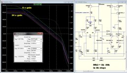
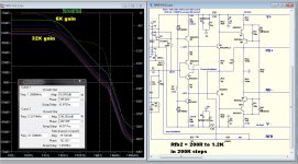
CFA - VFA CLG
Never compared the two over a wide range of FB R ratio's.
Many ask me to re-compensate for a custom gain. (pre-amps /KIDS! )
I have accommodated them for my VFA's , but never "warped" my
new CFA designs like this.
Interesting ... (below 1-2) .
The VFA remains at least marginally stable
at a real low resistor ratio (6X - 820R/5K). This may not be representative
of ALL VFA's , as this one has lead/lag/miller - "fancy" 😀
The CFA "bombs out" with a low ratio (39R/200 = 5X) .. oscillates like
a "pig"... 😀 would have to degenerate the input pair more or increase
C to get something workable. 🙁
Ahh ... an actual "drawback" for a CFA design. 😛
OS
Attachments
Everything on the subject (what is CFA)was told 20 or more years ago. I still do not understand this semantic discussion. Why not to stick with design suggestions and comments? Do we need so many pub oriented threads?
VFA, with "current on demand" properties similar to CFA.Well, which is it?
Cheers, E.
Interesting ... (below 1-2) .
The VFA remains at least marginally stable
at a real low resistor ratio (6X - 820R/5K). This may not be representative
of ALL VFA's , as this one has lead/lag/miller - "fancy" 😀
The CFA "bombs out" with a low ratio (39R/200 = 5X) .. oscillates like
a "pig"... 😀 would have to degenerate the input pair more or increase
C to get something workable. 🙁
Ahh ... an actual "drawback" for a CFA design. 😛
OS
My knee jerk reaction from experience is that you have a large peak in the response, too.
-RNM
Low port input z is just one part of the operation of a current feedback mode. That alone does not define the topology and operation as CFA.
When I was saying that low inverting input impedance is not a sufficient condition to get a CFA, somebody was protesting. When I'm stating what is a necessary and sufficient condition to get a CFA, somebody else was protesting. When I'm saying that a typical audio power amplifier is only 5-10% CFA, yet somebody else protests
. When I'm talking the very basic of the CFA theory, somebody asks me to shut down my pie hole and build something. When I'm building something, somebody else protests about being a useless amplifier.But's it's ok, this is part of the game and the fun. It's the price of touching the sacred cows
.- Home
- Amplifiers
- Solid State
- CFA Topology Audio Amplifiers