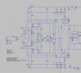
You are right, and it is very easy to listen with/without servo, to figure out if any character's change in the reproduction.Perhaps the misconception is that the IC will inject noise or other "badness" into the diamond. With just DC and a couple nV of AC being fed back through a 470K resistor - it truly amounts to nothing.
The only thing to take care of, on my opinion, is the low pass filter low enough to not introduce phase change in the audio band. Means < 2Hz ? And that, in this condition, DC offset stay in reasonable values, <10 mV ?
I would always advise using a good quality pot. The open frame types are not good enough for quality audio IMV. Use a Bourns or something of that caliber. They are sealed and usually have a plastic resistive element.
The servo or offset signal is also being shunted by the lower side of the feedback leg, so AC noise wise, it really is not a problem.
The servo or offset signal is also being shunted by the lower side of the feedback leg, so AC noise wise, it really is not a problem.
Not if DC servo is connected like this http://www.diyaudio.com/forums/solid-state/240712-cfa-topology-audio-amplifiers-374.html#post3771725
Bob Cordell (3851)
Having a negative output impedance from a power amplifier can sometimes be a useful tool for altering the speaker damping. However, bear in mind that both closed-box and vented systems are designed and voiced assuming a normal amplifier with fairly high damping factor. The Qts of the woofer will be decreased by a negative amplifier output impedance and alter the bass alignment. There can also sometimes be some interactions with crossovers if a negative output impedance is put at the amplifier output.
Bob!
Negative resistance is intended to compensate for the resistance of the speaker cable, see Patent: Patent US4441085, N03F 1/34, publ. 03.04.1984
then cable simply will not exist!
Here is another example of a negative output resistance
[/URL][/IMG]
http://radikal.ru/fp/f86f43e5fbb04b07a76a558e6e2d044c][/URL]
best regards
Petr
Hi Petr,
Thanks for clarifying. I guess I was implicitly assuming that the resistance of quality speaker cable of reasonable length would be less than 0.1 ohm.
Cheers,
Bob
Dadod, it's still shunted by the source output impedance (assume 50 to 100 ohms) and the filter input resistor which in this case is 220 ohms. So about 1000x shunt.
OS has chosen to do it this way - another option is to inject the servo current into the feedback summing junction. The shunting effect then is greater.
OS has chosen to do it this way - another option is to inject the servo current into the feedback summing junction. The shunting effect then is greater.
Well seen.Dadod, it's still shunted by the source output impedance (assume 50 to 100 ohms) and the filter input resistor which in this case is 220 ohms. So about 1000x shunt.
You would think I feel insulted by this ad hominem argument. In fact I am not at all. Your comments clearly defines the high end audio as exactly what it is today: a fashion based niche, full of voodoo knowledge, self invented for the sole purpose of surviving at any cost. Therefore, I believe they are helpful for everybody around. I've marked below (where possible) my comments as TRUE or FALSE for each of your statements
- The big problem with you is you believe electronic for audio is a science. TRUE
- An imperfect assembly of imperfect components, witch react with a lot of evils to a huge number of various environment you can't put on paper. FALSE
- I'm sorry to inform you that simulator is a nice tool, but just a caricature. TRUE and FALSE
- I'm sorry to inform-you that we know very little about the way our brain+ears works and can be fooled. FALSE
- I'm very sorry to inform you we know very little about how our beloved and imperfect musical signals are destroyed in our imperfect electronic assemblies. FALSE
- I'm sorry to inform you that, as long you will be the 'believer' you are, yes this is what you are, you will never be a good designer for audio. TRUE 😀
- Because all the great designers i had met in my life, with no exceptions, were modest, doubtful, curious, open minded, experienced, with respect for others. FALSE
- They lie on what they can see, listen, reproduce. And they had done this a lot during years, endlessly. (And, with no doubt, J.C. is one of them). TRUE
- You ? You are here in front of a lot of great audio designers. FALSE
- They all know what you just have learned at school or in books: A theoretical knowledge, just information, not knowledge, a very little part of the game. FALSE
- They have experience. TRUE
- Do-you have respect for what they share ? No. TRUE and FALSE
- Do-you ask yourself the question: Why are they so exited with CFAs ? TRUE, yes I do
- A lot of people reports similar experience, did this question your certitudes ? FALSE, I don't have any
- Did-you decided to listen to some samples of CFAs, in order to see what is behind or about ? Never. FALSE
- You just pontificate against a topology that you have never experienced. FALSE
- I'm sorry, but you are the one who don't believe UFOs exists. TRUE, TRUE and then TRUE again.
No more than your permanent contempt for this thread's participants. Your responses enlight perfectly the thin nuances of your thoughts.You would think I feel insulted by this ad hominem argument.
Some of them are sooo funny, like the second one...
Dadod, it's still shunted by the source output impedance (assume 50 to 100 ohms) and the filter input resistor which in this case is 220 ohms. So about 1000x shunt.
OS has chosen to do it this way - another option is to inject the servo current into the feedback summing junction. The shunting effect then is greater.
It depends of the source output impedance, if you use valve pre amp it is not so low.
I prefer the feedback summing junction.
Generally, it is best Not to inject control signal with ac/music signal. The servo control signal is best injected at CCS or place buffered/isolated from ac signal path. Or, select devices for acceptable offset at output (no trim pot) and use servo to control thermal drift... which should be low also.
That's the perfectionist view.
If OPS signal is filtered enough so it does not introduce noise or LF artifacts/ group delay etc.... then it is OK to apply control signal with ac music signal. Often it takes multiple stages of LP filtering.
Thx-RNMarsh
That's the perfectionist view.
If OPS signal is filtered enough so it does not introduce noise or LF artifacts/ group delay etc.... then it is OK to apply control signal with ac music signal. Often it takes multiple stages of LP filtering.
Thx-RNMarsh
Last edited:
Generally, it is best Not to inject control signal with ac/music signal.
Thx-RNMarsh
Hi Richard,
This makes no sense to me. Please explain.
Cheers,
Bob
According there is no musical signal in the servo output (a pure utopia) we would like to make sure the Servo output impedance is flat enough over all the audio band ?This makes no sense to me.
The Richard's idea is to add some isolation between servo DC and audio, despite, at the end, the result will be the same ?
As i said, it is so easy to compare instant with/without the servo to have no metaphysical questions about sound degradation.
Or spend some hours on measurements for deaf people 🙂
Last edited:
Generally, it is best Not to inject control signal with ac/music signal. The servo control signal is best injected at CCS or place buffered/isolated from ac signal path. Or, select devices for acceptable offset at output (no trim pot) and use servo to control thermal drift... which should be low also.
That's the perfectionist view.
If OPS signal is filtered enough so it does not introduce noise or LF artifacts/ group delay etc.... then it is OK to apply control signal with ac music signal. Often it takes multiple stages of LP filtering.
Thx-RNMarsh
I tend to be one of those perfectionists. 😀
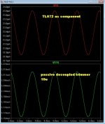
A simulated passive/trimmer based offset is just as "dirty" , if
derived from a local source .... like basic zener regulators.
(below) shows that there is an "audio component" in both techniques.
With the passive's , you rely on the zener's regulation and just 1 capacitor.
If you were to go "anal" and use a precision external reference , I suppose
you could obtain "utopia" . 😀
On the top plot (TL072) , you actually have the PSRR of the op-amp (100db)
"cleaning up" the zeners (regulation).
For the "purists" .... ha ha , you have a VFA cleaning up the offset
"mess" of a CFA. 😀
OS
Attachments
Servo injected via ccs
Cool beans , to control CCS reference w/ the servo.😎
Even in this case , with the op-amp using FAR more current , it's
PSRR determines the level of "utopia".
OS
Last edited:
servo
A perfectly isolated servo from the signal path will have no effect on the output offset at all. 😀
A perfectly isolated servo from the signal path will have no effect on the output offset at all. 😀
Member
Joined 2009
Paid Member
Because all the great designers i had met in my life, with no exceptions, were modest,
hmmmm....
Besides, it doesn't always help to be modest
Last edited:
- Home
- Amplifiers
- Solid State
- CFA Topology Audio Amplifiers

