Think before post...
I clearly described the circuit (in words) before posting .05%...
" LTP/bootstrapped VAS".
NO mention of beta enhancement or other linn "frills".
The "decked out" Linn is the one you decribe. I ALSO mentioned that one ..
"LTP/cascode/CM/2 CCS/beta enhancement" . THIS gets you the mentioned
.001%THD20.
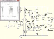
Perhaps a schematic will will be more clear.
A very common, reliable VFA circuit (below-THD20 included).
I could of said "Hugh's amp" , but then you do not know him.
That "simple linn" is the VFA anology to the CFA "peeceebee" with minimal active devices.
Both have sub par PSRR ,but the CFA has much better slew/THD20.
Both can be augmented with additional circuitry. The VFA with CM/CCS/beta
enhancement ... the CFA with basic regulation.
OS
By waly - I said if the .05% is correct. Which IMO is not, it only shows an incompetent design. D. Self got 0.001% distortions with a classic VFA Lin topology (aka "blameless").
I clearly described the circuit (in words) before posting .05%...
" LTP/bootstrapped VAS".
NO mention of beta enhancement or other linn "frills".
The "decked out" Linn is the one you decribe. I ALSO mentioned that one ..
"LTP/cascode/CM/2 CCS/beta enhancement" . THIS gets you the mentioned
.001%THD20.
Perhaps a schematic will will be more clear.
A very common, reliable VFA circuit (below-THD20 included).
I could of said "Hugh's amp" , but then you do not know him.
That "simple linn" is the VFA anology to the CFA "peeceebee" with minimal active devices.
Both have sub par PSRR ,but the CFA has much better slew/THD20.
Both can be augmented with additional circuitry. The VFA with CM/CCS/beta
enhancement ... the CFA with basic regulation.
OS
Attachments
I clearly described the circuit (in words) before posting .05%...
" LTP/bootstrapped VAS".
NO mention of beta enhancement or other linn "frills".
The "decked out" Linn is the one you decribe. I ALSO mentioned that one ..
"LTP/cascode/CM/2 CCS/beta enhancement" . THIS gets you the mentioned
.001%THD20.
Perhaps a schematic will will be more clear.
A very common, reliable VFA circuit (below-THD20 included).
I could of said "Hugh's amp" , but then you do not know him.
That "simple linn" is the VFA anology to the CFA "peeceebee" with minimal active devices.
Both have sub par PSRR ,but the CFA has much better slew/THD20.
Both can be augmented with additional circuitry. The VFA with CM/CCS/beta
enhancement ... the CFA with basic regulation.
OS
0.05% for that junk is a real performance. I would think no sane person should build this in the year of 2014, but I'm pretty sure some would disagree 😀.
Mind you, it has absolutely none of the distortions cancelling and negative feedback VFA properties that I mentioned.
Three key features make current-feedback amplifiers outstanding for audio.
Here's the Texas Instruments opinion on CFA:
"The TPA6120A2 is a high fidelity audio amplifier built on a current-feedback architecture. This high bandwidth,
extremely low noise device is ideal for high performance equipment. The better than 120 dB of dynamic range
exceeds the capabilities of the human ear, ensuring that nothing audible is lost due to the amplifier.
The solid design and performance of the TPA6120A2 ensures that music, not the amplifier, is heard.
Three key features make current-feedback amplifiers outstanding for audio.
The first feature is the high slew rate that prevents odd order distortion anomalies.
The second feature is current-on-demand at the output that enables the amplifier to respond quickly and linearly
when necessary without risk of output distortion. When large amounts of output power are suddenly needed, the amplifier
can respond extremely quickly without raising the noise floor of the system and degrading the signal-to-noise ratio.
The third feature is the gain-independent frequency response that allows the full bandwidth of the amplifier to be used
over a wide range of gain settings. The excess loop gain does not deteriorate at a rate of 20 dB/decade."
Here's the Texas Instruments opinion on CFA:
Three key features make current-feedback amplifiers outstanding for audio.
The first feature is the high slew rate that prevents odd order distortion anomalies.
The second feature is current-on-demand at the output that enables the amplifier to respond quickly and linearly when necessary without risk of output distortion. When large amounts of output power are suddenly needed, the amplifier can respond extremely quickly without raising the noise floor of the system and degrading the signal-to-noise ratio.
The third feature is the gain-independent frequency response that allows the full bandwidth of the amplifier to be used over a wide range of gain settings. The excess loop gain does not deteriorate at a rate of 20 dB/decade."
Don't you love the marketing hype 😀.
It is true that a low slew rate can create distortions. Not said in the ad: you don't need a CFA to reach the point of no slew induced distortions. As I already mentioned, 1V/uS for each peak output volt is more than enough.
"current-on-demand... to respond quickly and linearly when necessary without risk of output distortion" - quickly yes, linearly, not necessary. But besides, for audio, this is in fact never "necessary" 😀.
"the amplifier can respond extremely quickly without raising the noise floor of the system and degrading the signal-to-noise ratio" - uh-oh, I am not aware of any direct relationship between the slew rate and the noise, worth a question for the marketing heads that wrote this ad 😀.
"The third feature is the gain-independent frequency response that allows the full bandwidth of the amplifier to be used over a wide range of gain" - this is true for a headphone amplifier, with 6-12dB of gain. Not the case for high gain (>20-26dB) power amplifiers.
Fact is, TI repurposed a DSL driver (where indeed the combination of slew rate, gain independent frequency response, low noise, and high output current is critical) as a headphone amplifier, and is marketing it accordingly.
I mentioned the TPA6120 CFA as an example of (low power) application where CFAs are at par with the best VFAs, and where an attempt to build a discrete version, VFA or CFA, doesn't make much sense. Mind you, the topic is power amplifiers, and don't make me start ranting again about the VSSA.
Yus are all idiots & deaf ad nauseum
Or is this just part of your marketing campaign ie 'Yus are all idiots & deaf' ?
How about posting another USEFUL item to go with your 'improvement' on Edmond's stuff. We accept you probably won't ever post anything 'real life' 😱
.. but I'm sure your undoubted knowledge & wisdom might actually result in something useful .. even in SPICE world .. once you get away from 'Yus are all idiots & deaf'.
___________
For the rest of us, if we stop responding to Waly's ad nauseum 'Yus are all idiots & deaf' posts, he might get tired of that and actually post something useful. 🙂
Waly, presumably, there is some practical & useful info in these posts that will help us design better amplifiers, whether CFA or VFA.Don't you love when people are running out of technical arguments? No worries, I'm not hoping to spoil your marketing campaign.
Or is this just part of your marketing campaign ie 'Yus are all idiots & deaf' ?
How about posting another USEFUL item to go with your 'improvement' on Edmond's stuff. We accept you probably won't ever post anything 'real life' 😱
.. but I'm sure your undoubted knowledge & wisdom might actually result in something useful .. even in SPICE world .. once you get away from 'Yus are all idiots & deaf'.
___________
For the rest of us, if we stop responding to Waly's ad nauseum 'Yus are all idiots & deaf' posts, he might get tired of that and actually post something useful. 🙂
Last edited:
 pulled some posts, if you think we are not looking at this thread, you are wrong...personal attacks will earn bin time after this post...shoot the message and not the messenger....
I mentioned the TPA6120 CFA as an example of (low power) application where CFAs are at par with the best VFAs,
Do you have an example of 'the best VFA' that you were thinking of so we could all make this comparison?
To me its interesting that all the ADSL drivers I've seen have been CFB. And yes I already buy the argument that they're lower gain than poweramps 😀
ADSL drivers are interesting also from the point of view they're characterized by a different set of metrics - in my estimation including one metric which is closer to what's needed for characterizing audio amplifiers. To wit - MTPR. This uses a high crest factor multitone (255 discrete tone) waveform as stimulus - more music-like than the single sinewave so beloved of amp designers.
Anyone have MTPR measurement results for any VFA by any chance?
0.05% for that junk is a real performance. I would think no sane person should build this in the year of 2014, but I'm pretty sure some would disagree 😀.
Mind you, it has absolutely none of the distortions cancelling and negative feedback VFA properties that I mentioned.
That junk !!! That is the usually the first (VFA)amp a new DIY'er builds.
I built it ... so I'm an idiot. But ... It still works and will most likely outlive
it's electrolytic' s.
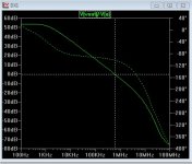
It DOES show VFA characteristics ... it PSRR is better than a simple
2 device CFA. It's OLG bode plot is like a VFA (below). It's EF2 has .5% THD,
so it's differential must be cancelling distortion.
Not fancy ... but ,it still is a VFA.
OS
Attachments
Depends on what you mean by "matching". Even in modern IC processes, n/p Vbe matching is at least one order of magnitude worse than n/n or p/p.
AFAIK, you made preamps and headphone CFAs, the discussion here is about power amplifiers. By far not the same thing, for low power a CFA DSL driver like the TPA6120 will drive any headphone set with ppm distortions, ultra low noise and a huge bandwidth. Building with discretes anything to match the TPA6120 is very difficult, if possible at all (not to mention the cost factor).
Modern processes needed in CFA's can match compliments for best performance a lot better than by a ten-fold order of magnitude.
Apparently, you don't know I did several power amps as well. Bipolar and MOSFET OPS. Up to 900W/4 at very low distortion.
....
Please get you facts straight if you are going to argue with me.
Thx-RNMarsh
Last edited:
Anyone have MTPR measurement results for any VFA by any chance?
Several people who monitor this subject have test equipment that can do multi-tone tests. I intend to do such tests with my Audio-Precision 2722 in 2014.
Thx-RNMarsh
Don't you love when people are running out of technical arguments? No worries, I'm not hoping to spoil your marketing campaign.
About sub ppm CFA amplifiers, you just made my point. Based on the results on this thread, try a blameless with 6MHz ULGF and 4 pairs of output devices running at 50W/8ohm output with +/-56V rails and see what you get, you'll be surprised.
Have fun
I closed my CFA design loop at ~3MHz and got 800 ppb at 20 kHz at 50 W. I get <3ppm at 400W from the same sim.
And no, the front end of a CFA does NOT go into class B if you take some simple steps - easy to do in a discrete power amp.
Get your facts straight Waly.
Last edited:
Several people who monitor this subject have test equipment that can do multi-tone tests. I intend to do such tests with my Audio-Precision 2722 in 2014.
Encouraging news, thank you. How many tones do you intend to use?
@Waly - curious. Why would anyone use 56 volt rails for a 50W/8R poweramp? I'd love to know the results of simming that for PSRR with four paralleled (or did you mean totem-poled?) devices. 😀
Last edited:
Encouraging news, thank you. How many tones do you intend to use?
I tore out the Dolby test option pcb and purchased/installed the IM option this summer. It is just for the multitone I want for the same reason... more like real music... a little bit, anyhow.
I haven't had time to read up or even try it yet.... but what ever the max number of tones is, you can be sure I'll use them all.
Thx-RNMarsh
Last edited:
Here's the Texas Instruments opinion on CFA:
The first feature is the high slew rate that prevents odd order distortion anomalies.
😎🙂
Thx-RNMarsh
I tore out the Dolby test option pcb and purchased/installed the IM option this summer. It is just for the multitone I want for the same reason... more like real music... a little bit, anyhow.
I haven't had time to read up or even try it yet.... but what ever the max number of tones is, you can be sure I'll use them all.
It was many years ago when I last played with an AP (dual domain), but as I recall they had a software utility to help compose multitone waveforms then. You'll need to check on the multitone performance of the DAC you use to generate the waveform, as it could easily be the bottleneck.
Don't you love when people are running out of technical arguments? No worries, I'm not hoping to spoil your marketing campaign.
About sub ppm CFA amplifiers, you just made my point. Based on the results on this thread, try a blameless with 6MHz ULGF and 4 pairs of output devices running at 50W/8ohm output with +/-56V rails and see what you get, you'll be surprised.
Have fun
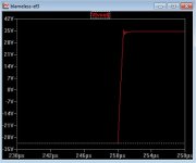
I did try the "honey badger" with 6mhz ULGF - I was not surprised(oscillation).
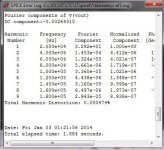
Using my frequently posted HK triple , the blameless really does well. Double
the slew at 3 mhz ULGF -140v/us (below 1) . and a cool 4 ppm at high power
3R load (Below 2 -thanks to the EF3).
The CFA's are really close at 10-20ppm - same setup.
But ... I can easily get them to run at 5+mhz ULGF - again , same setup.
I tried EVERYTHING to get over 200V/us out of the badger - NOPE....
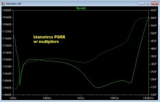
BTW - check this VFA's PSRR with the cap multipliers !! (last attachment)
This is the VFA's strongest point. Especially this one !
PS- another good candidate for the "rumble". Black/white -VFA/CFA ...
I don't discriminate - a good amp is a good amp 😀 .
OS
Attachments
With lower loop gains, as is the case with CFA's, I suspect you can close the loop at higher ULGF, which seems to be confirmed by your results above.
Reason why: with lower open loop gains, the phase acumulation at HF is less - so the output stage pole falls further below the 0 dB ULG than would be the case with a high loop gain VFA design. This translates directly into greater phase and gain margin and that can be traded for higher ULGF.
Reason why: with lower open loop gains, the phase acumulation at HF is less - so the output stage pole falls further below the 0 dB ULG than would be the case with a high loop gain VFA design. This translates directly into greater phase and gain margin and that can be traded for higher ULGF.
You know your stuff , Bonsai.
That's what I did. Every 10db I "shaved" off the gain , I could go that much
higher ULGF. Which , in turn .... lowered my THD20. Of the 3 compensation
schemes I used ,TMC gave the best results.
I even "tricked" the blameless with a little lead comp. - got to 4mhz with
slight instability (ringing - oscillation on a SW)
This tradeoff is far less evident in the NX/VSSA simulations. Just a
couple DB gave me a Mhz. CFA is less sensitive compensation- wise... "idiot
proof" .
These VFA's really do work much better with (this) EF3. I used 22/100pF
for TMC , I could not do this with the "base" badger simulation. VAS
loading is probably the culprit. 🙁
Soon , I'll be able to go "rapid fire" through all these excellent designs. 🙂
OS
With lower loop gains, as is the case with CFA's, I suspect you can close the loop at higher ULGF, which seems to be confirmed by your results above.
Reason why: with lower open loop gains, the phase acumulation at HF is less - so the output stage pole falls further below the 0 dB ULG than would be the case with a high loop gain VFA design. This translates directly into greater phase and gain margin and that can be traded for higher ULGF.
3.8Mhz is my best attempt so far but reckon using a lower distortion design in the first place with lower ULGF (1Mhz) is the better way to go. That way you can have decent stability (Simulated PM = 82 degrees with GM = 23dB) while still having single digit ppm distortion (simulated). Added complexity is the pay back.
I tore out the Dolby test option pcb and purchased/installed the IM option this summer. It is just for the multitone I want for the same reason... more like real music... a little bit, anyhow.
I haven't had time to read up or even try it yet.... but what ever the max number of tones is, you can be sure I'll use them all.
Thx-RNMarsh
Richard, AP has an ISO standard 31-tone multitone test that you should be able to run from the digital generator. I don't think you even need the IM board for that.
Jan
- Home
- Amplifiers
- Solid State
- CFA Topology Audio Amplifiers