If 'yus are all idiots & deaf' is your ideal of fun, I'm certain you will have a lot more fun on JC's Blowtorch thread.I am having fun, does this compute? Or is this not allowed on a public forum?
I seem to remember, I had a small hand in mythbusting .. about noise performance & THD of CFAs among other trivialities. Alas, my naive contributions appear to have been swamped by the 'yus are all idiots & deaf' posts.Speaking about contributing, I am patiently waiting to receive your own contribution to this CFA saga. So far, I haven't seen anything but peanut gallery and messages requesting people to work hard to do your homework in basic electronics.
Also, they used very simple circuits so were probably beneath your notice. 🙁
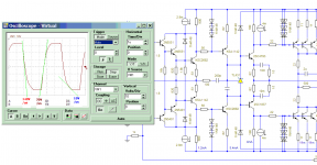
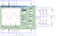
Bravo Waly 🙂 At last some firm (?) evidence that you not only read loadsa books but also actually build stuff 😀And because you asked, here's what I did today at work (not audio, of course): measuring the loop gain of a two pole compensated cmos op amp (a signal conditioning building block in one of my analog + DSP circuits). 3.6MHz ULGF, not bad for this process and slightly over 1mA Iq. About 45dB of loop gain to linearize. Ignore the LF (under 100KHz) phase, the scale is also wrong, should read 0 top -200 degrees bottom. For the final cut, I need to push the zero a little further in frequency to gain 10 degs of extra phase margin. BTW, I build the loop gain measurement jig myself.
With some luck, you might show us some useful stuff about amps on this thread before the next Millenium. Well done!
OK. I apologise for my snide remarks. I was grateful for your link to TPA6120 so not everything you post is useless.
I'm not sure why you object when people ask for clarification of your claims. Most people are unwilling to spend time & trouble investigating wild unstubstantiated claims. That clarification is requested is a sign of interest. ie your circuits/claims might actually be useful.
Would you rather your claims are dissed on purely theoretical grounds or 'yus are all idiots & deaf' lines?
If you haven't actually simmed/tried in 'real life' etc. .. it costs you nothing to say, "here's my suggestion but I haven't simmed/tried it in 'real life'."
It's called courtesy and honesty BTW.
Err.rh! I've just asked Waly to substantiate his claim that his circuit is better than Edmond's and received a less than satisfactory answer.I do think your comment seriously misrepresents Waly, he may think there's lots of idiots but he seems to have annoyed people precisely because he demands proper tests to support the "CFAs sound better"/"More slew rate sounds better" claims.
And AFAIK absolutely no such tests have been provided as evidence.
So can the unsubstantiated claims stop so that Waly doesn't spend his efforts to dispute them?
Then perhaps he will have more time for more productive topics.
Links in my #3526 post.
As a real DBLT bla bla guru in my previous life, I know how much time, effort and money would be required to substantiate "CFAs sound better" to whatever accuracy you might like. Hence I'm prepared to take such claims with a pinch of salt ... but also take the attitude that some listening tests are better than none.
However, Waly's claims re 'improvements' to Edmond's circuits are much simpler. He's either done the sims .. in which case, he will have numbers to report. Or he hasn't .. in which case he's just having fun with the truth 🙂
To his credit, there is less noise and more substance in his recent posts. I hope this trend continues.
Meanwhile, I intend to examine critically anything that comes out of this thread that might be useful for designing amps.
I hope no one thinks this attitude is wrong ... and that my questions are anything but my poor attempt get at the 'truth' whatever that is 🙂
If you can afford a decent analog scope then thats what I'd recommed. I would however take a 1 GS/s DSO over a 10 MHz scope any day. I think for an analog scope, go for at least 100 MHz, but if you can go to 200 MHz thats better.
Picking Capacitors - Walter G. Jung and Richard Marsha quick search for "Marsh" at the AES library doesn't give any articles by Richard, but does show hits where others cited the "Picking Capacitors" articles
I mistaken, but i believed it had been published by the American hype private audio club. If not, of course, this study has no value.
Last edited:
😀There presides the true master of 'yus are all idiots & deaf'. 😱
Well, about components sound, people, reviews, audio organizations et. can say what they want, but we can measure and hear differences between different resistances material (Carbon, thick carbon, thick film, metal oxyde, wirewound etc...).
We can measure and hear differences between various caps materials. And even between different brand of lytics.
This said, i will not buy audiophile brands, for ten time the price of the same technology industrial device. The rule here too is, as always, to use the right device for what we attempt to do... at the best price.
Last edited:
mythical unicorns
Hi Richard,
I suppose you mean this response. Well, I'm flabbergasted. This circuit is not only wrong in every respect, but the person who invented it missed, ignored or didn't understand my points:
1. No CCS noise cancellation, as the collector currents of the input trannies have been isolated from the next stage (by means of Q2 and Q5)*.
2. Most likely it does not comply with the 'E. Stuart' condition, as Ic wasn't specified. With RE = 50 Ohms, Ic should be 0.25mA to meet this condition, but nobody would run a diamond buffer at such a low current.
More generally:
3. Since the base of Q7 and Q8 are held at a fixed voltage, instead of a sliding voltage, the cascodes are far from optimal.
4. And what about this remark: 'You now can run the input diamond buffer as hot as you like (which could be a good idea, for lower voltage noise)'
Apart from an increased current noise, pretty ineffective with RE=100 respectively 50 Ohms and other sources of noise.
Indeed, these 'improvements' are mythical unicorns, thus no need to adjust my ignore list. 🙂
Cheers, E.
* BTW, I wouldn't be surprised if the idea was blindly copied from syn08's output stage.
Edmond, Waly posted a response to your #3135 circuits claiming 'improvements'.
I queried this in #3472 and other posts.. His eventual reply is in #3473. which was less than helpful. 🙁
Reading between the lines, I think it is likely that he has simmed his own circuit but as he doesn't present his PSSR & THD results, there is no evidence. We have to take his word for it.
I think its unlikely he has simmed a version of your circuits for comparison but I might be wrong.
So at the moment, the 'improvements' are mythical unicorns 🙂
My naive visible inspections of his & your circuits suggest little or no 'improvement'.
[...]
Hi Richard,
I suppose you mean this response. Well, I'm flabbergasted. This circuit is not only wrong in every respect, but the person who invented it missed, ignored or didn't understand my points:
1. No CCS noise cancellation, as the collector currents of the input trannies have been isolated from the next stage (by means of Q2 and Q5)*.
2. Most likely it does not comply with the 'E. Stuart' condition, as Ic wasn't specified. With RE = 50 Ohms, Ic should be 0.25mA to meet this condition, but nobody would run a diamond buffer at such a low current.
More generally:
3. Since the base of Q7 and Q8 are held at a fixed voltage, instead of a sliding voltage, the cascodes are far from optimal.
4. And what about this remark: 'You now can run the input diamond buffer as hot as you like (which could be a good idea, for lower voltage noise)'
Apart from an increased current noise, pretty ineffective with RE=100 respectively 50 Ohms and other sources of noise.
Indeed, these 'improvements' are mythical unicorns, thus no need to adjust my ignore list. 🙂
Cheers, E.
* BTW, I wouldn't be surprised if the idea was blindly copied from syn08's output stage.
1. No CCS noise cancellation, as the collector currents of the input trannies have been isolated from the next stage (by means of Q2 and Q5)*.
2. Most likely it does not comply with the 'E. Stuart' condition, as Ic wasn't specified. With RE = 50 Ohms, Ic should be 0.25mA to meet this condition, but nobody would run a diamond buffer at such a low current.
More generally:
3. Since the base of Q7 and Q8 are held at a fixed voltage, instead of a sliding voltage, the cascodes are far from optimal.
4. And what about this remark: 'You now can run the input diamond buffer as hot as you like (which could be a good idea, for lower voltage noise)'
Apart from an increased current noise, pretty ineffective with RE=100 respectively 50 Ohms and other sources of noise.
1. CCS noise sources are uncorrelated, you can't cancel two noise sources even with 100% identical stages. In general, the only way you can cancel noise is to make one source as common mode, therefore rejected by the CMRR.
2. Your "invention" of RE = 0.5/gm = 0.5 VT / Ic or 13mV / Ic is well known as a condition for minimum IM3 distortion in RF amplifiers. This condition (as much as the Oliver optimal bias for power stages) are both large signal conditions, where the transconductance variation due to the large signal swings are important. I doubt it has any significant impact in small signal stages, unless you can provide a reference. Mind you, the tanh principle is a completely different story.
3. From day one, the whole point of cascodes is to use a pair of devices, one with high beta (Q3/Q6) the other with high Early voltage (Q7/Q8). In this way, an equivalent transistor is created, that has both an equivalent high beta and high Early voltage. A reference to a better/different way to implement a cascode would be appreciated.
4. 100ohm equivalent is 1.2nV/rtHz. Would work for a moving magnet RIAA preamplifier, why would that be a problem for a power amplifier.
You conveniently skipped the really interesting part: the improved overload recovery. But then please don't bother, I feel very comfortable on your ignore list.
BTW, that input stage configuration with two extra transistors was first mentioned (at least that's where I got it from) by a well respected former member of this forum, and true simulation guru. We are all indebted to him for the excellent Level 5 2SK1530/2SJ201 mosfet and the 2SC5200/2SA1381 bipolar simulation models. His name is Andy Connor (Andy_c). BZZZZZT!
Member
Joined 2009
Paid Member
I miss Andyc - he was a very smart person and provide a lot of useful input.
I don't mind people who challenge ideas, thoughts and observations - it keeps us honest. Unfortunately, a forum, like e-mail, is a difficult medium to communicate in without issues. Some posts still read like 'advertisements' and others are 'too critical' - something to learn.
I don't mind people who challenge ideas, thoughts and observations - it keeps us honest. Unfortunately, a forum, like e-mail, is a difficult medium to communicate in without issues. Some posts still read like 'advertisements' and others are 'too critical' - something to learn.
I miss Andyc - he was a very smart person and provide a lot of useful input.
I don't mind people who challenge ideas, thoughts and observations - it keeps us honest. Unfortunately, a forum, like e-mail, is a difficult medium to communicate in without issues. Some posts still read like 'advertisements' and others are 'too critical' - something to learn.
I also miss Andy and wish he would come back. I am indebted to him for some of the simulation material in my book. He was also kind enough to proof-read my whole book.
Cheers,
Bob
1V/uS for each peak output is good enough for your ears, not my ears. Absolutely, your ears and my ears is different. I know the different how my VFA amp with 0,06% THD sounding againts VSSA.
The need of 1V/uS for each peak output is marketing only 😀.
It is rather 1V/us/Vpk , about 40V/us for a 100W RMS amplifier
and still Waly is quite generous since even half this value is enough.
Indeed if you hear a difference then it means that you can
hear sounds up to 100KHz or so , that s basicaly what are
claiming people who pretend to hear the difference between
two such slew rates...
Hi wahab,
You are correct; 1v/us/Vpk is fine. At that SR, there are other, much more important, things to focus on in amplifier design.
Cheers,
Bob
I also miss Andy and wish he would come back. I am indebted to him for some of the simulation material in my book. He was also kind enough to proof-read my whole book.
Cheers,
Bob
Yes, Andy was a real gentleman. He gave me my first .asc file (attachment) and
was the absolute antithesis of Glen K. 😀 Much thanks to him !
Most of the expressions I use in LT spice are his.
OS
Attachments
No doubt i can hear-it. Even in my old age. Not like a sound, but like a discomfort.Indeed if you hear a difference then it means that you can hear sounds up to 100KHz or so ,
An other thing, it was a common practice, in recording studios, to use high Q >=40Khz bell filters to bring more air to some female voices, while nobody is able to hear such a frequency, neither most of the speakers to reproduce them...
Phase changes... Added distortions ?
Again here, the scientific approach is not to refer to books, but to experiment. May-be our ears are more sensible to energy (square waves surface) than pure sins that don't exists in nature. In the same spirit, listen to the difference between the same amp with square waves overshoot (fatiguing or detailed) and the same one with no such a defect. While the harmonic difference is way upper than our sinus limit ability.
May-be it is the change of the acceleration speed of speaker's membranes, or their fractioning, or IM, i don't know.
Now, about what is the slew-rate limit to reach, i don't know more than the distortion limit. All this deserve serious studies, Fletcher & Munson like, witch, as far as i know, has not been done.
In fact we know very little about the way our hearings works. It is a combination of mechanical (ears) and processing (brain).
One thing is for sure, extrapolating or referring to our ability to discriminates high frequencies sinus waves -this ability highly depends of levels- is a non acceptable simplification.
Last edited:
What you are hearing, as regards the discomfort factor, is electronics misbehaving - I've spent many years altering their behaviour, by improving the environment in which they work, and their ability to ignore 'noise' around them - and every time you do that the 'comfort factor' improves, to the point where very messy, 'difficult' recordings can be played back at high SPLs, with zero discomfort ...
What is electronics misbehaving and how to measure-it ?What you are hearing, as regards the discomfort factor, is electronics misbehaving -
Well, it seems obvious, indeed, that if you have a 100KHz oscillation out of you amp, there is somewhere an electronic problem in your system. 😛
The thing is, the misbehaviour may be transient in nature, it may not be a steady oscillation always there for you to pick happening. So, connect probes to key areas and monitor and record that information via a data capture system, while the system is playing testing material - a bit involved, yes, but it may give one key insights as to what's happening under the hood, in real circumstances ...
Tom Danley mentioned doing this in a casual way a couple of times, and, getting a surprise at seeing quite severe misbehaviour
Tom Danley mentioned doing this in a casual way a couple of times, and, getting a surprise at seeing quite severe misbehaviour
What you are hearing, as regards the discomfort factor, is electronics misbehaving - I've spent many years altering their behaviour, by improving the environment in which they work, and their ability to ignore 'noise' around them - and every time you do that the 'comfort factor' improves, to the point where very messy, 'difficult' recordings can be played back at high SPLs, with zero discomfort ...
Yes , I used a CFP Vbe on one of my amps ... it just oscillated "a little
bit" and only did so sometimes. It did not affect OP bias or heat the Zoble.
But ... when it did misbehave ... I really lost interest in music - I literally
subconsciously made the decision of ending my listening.
NO CFP's for me again 😀 . 🙁
OS
- Home
- Amplifiers
- Solid State
- CFA Topology Audio Amplifiers