Man, I'd be hesitant to put another signal transformer in an amp like that which will need a fair amount of feedback to make the whole thing work properly!
Man, I'd be hesitant to put another signal transformer in an amp like that which will need a fair amount of feedback to make the whole thing work properly!
--------------------------------------------
How So?🙂
--------------------------------------------
How So?🙂
Transformers always have high and low frequency poles, that tend not to be too far out of the audio band. Adding too many poles inside a feedback loop is pressing one’s luck.
Time to move on & use your imagination. No problem at all driving those CFs with any garden variety RC coupled phase inverter. I've done it, so can you.😀
And than some NFB, same as any other ordinary PP circuit. Where is your problem??🙄
And than some NFB, same as any other ordinary PP circuit. Where is your problem??🙄
I *would* use RC coupling at the followers inputs. Especially when the followers drive pentodes. Driving triodes, one could make the case for needing the extra voltage swing that the transformer drive provides. Then you’ve got to deal with the transformers frequency response. Be prepared to spend some money if you want something that won’t eat phase margin for breakfast. I’m a fan of not making things harder (or more expensive) than they have to be.
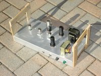
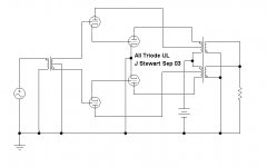
PP Class AB2 6V6s, CF Driven Grids
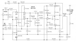
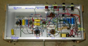
This is one of the amps I've built using CFs to drive the output tube grids. The input section is a differential stage, all connected as a PP cascode. Not a mu-follower as some might see it in error. That way the front end has pentode gain but a triode noise figure. And it can be driven from a differential source if desired. And the effect of ground loops can be minimized.
The second stage is PP 4BQ7 cathode followers driving straight into the control grids of PP 6V6’s. And they do look a lot like 6N7s! The heaters of the 4BQ7s are way off ground so run from the 5V winding on the PT. The PS is SS.
So all the way thru, differential, 6V6s running Class AB2. The use of 4BQ7 & 6BQ7 in audio may surprise some. In earlier work I found them to be damn near as good as 6SL7 & 6SN7 at a ¼ of the cost. Something to think about.
The Hammond 125E is set for a steeper loadline in order to match Class AB2 conditions.
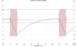
The scope trace shews a One KHz signal superimposed on the B+, offset from zero. That way PS sag is seen as the signal is applied thru an analogue burst gate.
The NFB is over one gain stage only to the upper cascode grids. One RC coupling, so LF stability should be unconditional.
On a ~350 Volt regulated PS this thing can make 26 Watts. Measured by a MetraHit 29S Precision DMM & Wattmeter. At low level it is running Class A. That makes for a lot of headroom.
Keep in mind this amp is meant from the start to be experimental, something to try a few ideas. And sounds great on any good speaker system. Better or not than something else, who knows!😀
This is one of the amps I've built using CFs to drive the output tube grids. The input section is a differential stage, all connected as a PP cascode. Not a mu-follower as some might see it in error. That way the front end has pentode gain but a triode noise figure. And it can be driven from a differential source if desired. And the effect of ground loops can be minimized.
The second stage is PP 4BQ7 cathode followers driving straight into the control grids of PP 6V6’s. And they do look a lot like 6N7s! The heaters of the 4BQ7s are way off ground so run from the 5V winding on the PT. The PS is SS.
So all the way thru, differential, 6V6s running Class AB2. The use of 4BQ7 & 6BQ7 in audio may surprise some. In earlier work I found them to be damn near as good as 6SL7 & 6SN7 at a ¼ of the cost. Something to think about.
The Hammond 125E is set for a steeper loadline in order to match Class AB2 conditions.
The scope trace shews a One KHz signal superimposed on the B+, offset from zero. That way PS sag is seen as the signal is applied thru an analogue burst gate.
The NFB is over one gain stage only to the upper cascode grids. One RC coupling, so LF stability should be unconditional.
On a ~350 Volt regulated PS this thing can make 26 Watts. Measured by a MetraHit 29S Precision DMM & Wattmeter. At low level it is running Class A. That makes for a lot of headroom.
Keep in mind this amp is meant from the start to be experimental, something to try a few ideas. And sounds great on any good speaker system. Better or not than something else, who knows!😀
Attachments
Last edited:
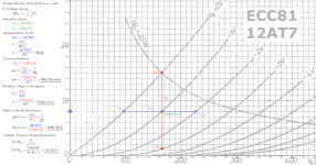
Because the data from the specsheets did not match my particular usage and because my knowledge about the dynamic parameters of the triodes were somewhat thin, I made this Geogebra-thingy which can calculate the parameters (picture attached). 12AT7 is shown as example, but all of the suggested triodes can be selected with the selectbox.
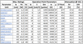
Having run the suggested double-triodes that dosen't take a ton of heater current, the comparison table looks rather different (picture attached).
Regards spuncut
Having run the suggested double-triodes that dosen't take a ton of heater current, the comparison table looks rather different (picture attached).
Regards spuncut
Attachments
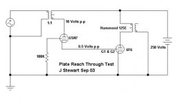
Dynamic Coupled Circuit from the Late 1930s
The earliest circuit of this kind I looked at was based on the 6AC5G Positive bias triode, driven by a low or medium mu CF. By 2003 when I was trying this the 6AC5 was expensive. But there was an easy way around that problem. Most of the ordinary pentodes such as 6K6 & 6F6 have a rather high mu with grids one & two strapped together. For example, the 6F6 has a mu of about 50 in this connexion.
I had many 6F6s in my stash, so that was the choice for the experiment. My objective was to create a virtual pentode with the 6F6 G1 & G2 triode strapped & a suitable driver CF. I used a 6SN7, both sections in parallel as the driver CF. The test was setup to look at FB thru the plate of the 6SN7, in this hookup the 6SN7 plate looks like the screen of the virtual pentode created. The information I needed was all with regard to the AC signal. I didn't check any of the resulting currents.
But looking at my results today I see that the cathodes of the paralleled 6SN7 were 12.25V off common. With a 250V plate supply we can read off the 6SN7 data sheet the total grid current into the 6F6 G1 & G2 would be ~4 mA.
Setting up the test is straightforward, no problems as long as all the leads are short. All powered by a common bench supply. A simple setup like this with one of your 807s would provide much of the data you need.🙂
Attachments

I am designing an AB2 amp with 807-tubes.
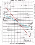
Good for you. I thought of doing that, but didn't need that much power, so I went with Class AB1 instead. If you consult the STC 807 Report (attached) you can see that the last column gives the highest power out with the lowest THD, so that's the one I'd go with. The 807 isn't a hard load, even when you take the control grids into positive territory.
At the desired output power I need to drive the grids toward +10V. At this voltage the grids form a voltagedependant resistor, which can be calculated at approx 1100Ohms at +5V and approx 700Ohms at +10V. At +10V the cathode folower should be able to deliver 15mA to the grid plus 5mA to a cascode current sink in the Cathode. So I need a triode with high µ and low ra for a cathode folower to meet these demands.
No you don't. For triodes, a high u-Factor works against current demand. The grid drivers are an active pull-up/passive pull-down circuit. For the vast majority of triodes, the high u comes from making the rp very high. Think the 12AX7 with its rp= 66K (design nominal). That makes for high voltage gain, but at the expense of current.
For Class AB2 grid drivers, I'd definitely go with a power MOSFET. The current supply capabilities, even at very low drain currents, is much greater than any hollow state device. The STC Report also recommends that the grid driver has a Zo <= 500R. A power MOSFET will give a Zo that's in single digits.
If you just have to have a cathode follower, you could possibly use a 6SN7. With the design nominal rp= 7K7, you'd need a VPK= 250V, and the Zo would be around 360R, so that would fulfill the requirements as laid out in the STC Report. However, you'd be better off using as grid drivers cathode followers made from types like the 6BX7. The rp= 1K3, and with a u= 10, the Zo= 118R, much better than the 6SN7. This type is a dual triode originally intended for TV vertical oscillator/output duty. There are other types along the same idea as the 6BX7. Another possibility is the 6AS7 -- a dial triode intended for series pass duty. Its plate resistance is much lower (280R) and with a high current capability.
It still would be inferior to a Source Follower: much lower Zo, and it doesn't need another hole in the chassis, and doesn't add a load to the heater xfmr.
For this design, you also need good screen voltage regulation. That's always a good thing to include, even though it was much neglected back in "the day". Even a string of VR tubes is better than nothing, but an active voltage regulator is best of all. We can do that as we don't have to answer to the pencil pushers and their demands to cheapen the design.
807s also like to make lots of nasty higher order harmonics, so you will be needing NFB to clean up the messes. Local NFB around the 807s is a good idea, and add enough gNFB to clean everything up. Also, include screen and plate stoppers as the 807 likes to make snivets when the plates cut off. Once you get the harmonics under control, these sound very good.
Attachments
- Home
- Amplifiers
- Tubes / Valves
- CF-driver for 807 AB2 Amp