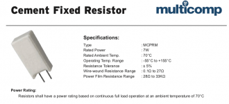
Anyone know what the maximum recomended operating tempurature of a 5 watt sand/cement/ceramic what ever you call the little white coffin type resistors is??
I am working on another SWR bass amp that failed because the resistors got so hot they melted the solder!!!
These amps use two 5 watt 1100 ohm resistors piggybacked and two 7.5 volt zeners in series to drop the +/- 75V down to +/-15v
I measured over 200 deg F / 100 Deg C right on the resistor body! that seems a little too hot for me!
I also noticed that the flux around the resistor legs where they are soldered together was bubbling!
This really seems like a serious design error if these resistors are running that hot. thats 2 amps now that have failed for the same reason. this one only partially failed. It was exhibiting odd performance fluctuations. sometimes it would run fine, others, it had no power and ran very hot. I found that when one of the resistors would lose contact, the amp would oscillate at full power! NASTY! Luckily we caught the problem before the amp went POOOF!
I have to find a cost effective solution for these things. there just isnt any room in there to mount 10 watt resistors.
Im still working on the pass regulator boards, havent had any time to test them yet however.
Zc
100 deg C is likely within their limits, but solder usually melts
just below 190 deg C, so it looks like your wire is getting
hotter than your resistor. 😕
just below 190 deg C, so it looks like your wire is getting
hotter than your resistor. 😕
Hi Zero Cool,
They're running about 2/3 capacity if the supply is in fact 75V. They will crack out of their coffin (open side?) with expansion and contraction unless it's pinned down - which is the best way so the cement side is exposed to the air for best dissipation. More worrying is the solder boiling - you'll have a dry joint in no time and there gous that 15V supply.
The answer is to either reduce the current or voltage. You could probably add about 150R 5W in series with them and see if all is OK operationally.
Cheers,
Greg
So, by "piggybacked" do you mean in parallel?
If so, you have 60V across each resistor (75-15).
So power dissipated by each resistor is (60^2)/1100,
which is approximately 3.2727 Watts.
Even if the zeners were shot and the resistors were
straight across the 75V, you'd have ~5.1136 W.
The latter is pushing it a bit but should not result in
what you're seeing.
The 3.27W scenario should be OK and not cause what
you're seeing. Of course, the usual caveats about adequate
ventillation apply. One could place these off the
PC board, as mentioned to allow better dissipation.
There must be something else going on.
What does 5W mean ?
Random thoughts here ...
A 5 watt resistor is rated at 5 watts @ 25 deg C (I think) so if the temperature inside the amp is say 40 deg C then 3 watts dissipation is probably too much.
Having said that I have seen lots of design faults (browned boards on well known brands) where heat is a problem. So you may not have a circuit fault, just a design issue.
If the resistors are soldered hard on the board they should be lifted to clear the board by 5mm or so. I have in the past attached a heatsink to resistors to help with the cooling and of course assisting the ventilation will help too.
Good luck & cheers.
I've had the same problem on a low-voltage regulator for an old Kenwood receiver. I bought some Ohmite aluminum 25W resistors and mounted them to the chassis, and ran leads to the PC board.
The resistors stay nice and cool by sinking to the large chassis, and no more desoldering themselves with the 'remote' location.
The resistors stay nice and cool by sinking to the large chassis, and no more desoldering themselves with the 'remote' location.
as quasi says' heatsinks are nice.
thermal glue like artic silver ilumina is nice for cases like theese.
-Marius
thermal glue like artic silver ilumina is nice for cases like theese.
-Marius
> isnt any room in there to mount 10 watt resistors.
If "5W" resistors are cooking that bad with just 3.5W of heat in them, then it isn't the resistors, the space is too small.
Power resistors need LOTs of air-space around for the heat to run away. If they are jammed in a small space, bigger or higher-temp resistors are still going to run too hot. Your resistors are not too-small, so the space muct be too small.
Passive regulators, same heat, same problem. (Modern silicon "will" live past 100 degree C, even 200C, though it is a bad idea.)
Switching regulators would run cool, but I don't know a stock item for that job, and roll-yer-own is major work.
Does the +/-15V really need to be 108 milliAmps? Seems like a lot. But if so:
Move the resistors. Put them on the far side of the chassis, lead-length is not critical. Put them in a perf-metal dog-house behind or on top of the amp. If you don't find some open space, it's never going to be happy.
We could argue that it is a design flaw, but it lived-out its warranty so from the designer's viewpoint, it is a success. Now it is your job to ensure a long happy life.
And the schematic calls that a 550 ohm 10 watt resistor. Maybe a bit small for a 6.5 watt dissipation. I suspect they did it with a pair of 5 watters for the space - easier to stack two than mount one large one.
Nothing says you can't do what PRR said, mount something larger on the chassis wall. It is not in the signal path, so there is no issue of hte wires picking up noise. Or ruining stability.
I am an authorized SWR service center, we signed on a long time before Fender bought them, and I have not run into this being a problem. But I agree they do run very hot.
I agree with PRR on the current thing. The SM900 has the 550 ohm resistance, while the Stereo 800 has only one resistor at the 1100 ohms. (Both those models run their HV at +/-75.) That results in the same dissipation per resistor, but limits the current to half the other. What would happen if you replaced the two 1100 ohm parts with a pair of 2k parts? That would cut the dissipation in half, still fitting in the same spot. Or even a couple 1.5k.
Enzo said:And the schematic calls that a 550 ohm 10 watt resistor. Maybe a bit small for a 6.5 watt dissipation. I suspect they did it with a pair of 5 watters for the space - easier to stack two than mount one large one.
Nothing says you can't do what PRR said, mount something larger on the chassis wall. It is not in the signal path, so there is no issue of hte wires picking up noise. Or ruining stability.
I am an authorized SWR service center, we signed on a long time before Fender bought them, and I have not run into this being a problem. But I agree they do run very hot.
I agree with PRR on the current thing. The SM900 has the 550 ohm resistance, while the Stereo 800 has only one resistor at the 1100 ohms. (Both those models run their HV at +/-75.) That results in the same dissipation per resistor, but limits the current to half the other. What would happen if you replaced the two 1100 ohm parts with a pair of 2k parts? That would cut the dissipation in half, still fitting in the same spot. Or even a couple 1.5k.
The SM-900 has a pretty big front end so 108ma is believe able. there is a tube pre amp, 2 4 section parametric EQs, the crossover, master bass/treble controls, the direct/line out stage and the master control section. quite a bit of stuff in the front end.
The ST-800 is just a power amp so it doesnt have all the front end stuff.
I have not seen this problem with other SWR amps, just the SM-900 so far.
I have been using some 1.2K resistors instead of the 1.1k's and i have been changing the board layout so that both resistors lay flat, spaced above the PCB so both are radiating upwards. Previously they had one stacked on top of the other without any support between them. the bottom resistor was cooking the top resistor plus that big tall stack without any support would wiggle around and grack the solder connections.
I will experiment with some chassis mounted aluminum housed Dale resistors. while i work on the Pass reg circuit. i just need to score some 220 Mosfets to play with.
Zc
> 108ma is believable. there is a tube pre amp, 2 4 section parametric EQs, the crossover, master bass/treble controls, the direct/line out stage and the master control section. quite a bit of stuff in the front end
Well, the tubes either don't eat the +/-15V, or they pass fractional-mA current at such low voltage. 108mA is not enough to light heaters, so I assume they get fed some other way?
Two 4-section para-EQs could be 40 opamps, though space and economics suggest less.
Crossover, say 6 opamps.
Bass/treb controls are often one opamp, but say 2.
Say another 10 for master and output buffers.
40+6+2+10= say 60 opamps. As 15 quad-amp chips, it must look like a 1976 computer inside.
TL072 opamps are popular in instrument amps, eat 1.5mA each, 90mA. Yeah, you are around 100mA IF my SWAG chip-count is right.
Does it really have a dozen 14-pin or two dozen 8-pin chips inside?
You say tube. What powers its heater? Is there any chance of tapping that to make chip-power?
Or hiding a 22VCT 300mA transformer somewhere?
The usual issue is the leads are clipped too short. The resistor should sit about 1/4” above a PC board. That extra lead length allows some heat to dissipate before it reaches the solder joint. It also creates a higher thermal resistance to the joint, also decreasing the solder joint temperature. The other benefit is the increased heat dissipation from the resistor body. The longer leads often solve the unsolder problem.
Some wirewound resistors have really high operating temperatures, for example 275 degrees Celsius for these: https://nl.mouser.com/datasheet/2/427/VISH_S_A0002936691_1-2568490.pdf (These are also available with stand-offs for PCB mounting.) I think I've seen even higher operating temperature values for other models.
Anyway, resistors like that are bound to desolder themselves when their leads are too short.
Anyway, resistors like that are bound to desolder themselves when their leads are too short.
- Home
- Amplifiers
- Solid State
- Ceramic Resistor Max Temps?