Hi,
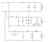
I have a feeling I am posting a stupid question but I'm recapping a Celestion Ditton 662 crossover for a friend and can't find equivalent values for the capacitors. In the attached schematic, I have c10 (30 uf) and C5 (72 uf) in parallel. Can I replace those with 22 uf and 80 uf given there is an inductor (L4) in between?
Thanks in advance for your answers.
Attachments

The Q factor of that bandstop filter, and it is probably on the higher side, has a dependence on the parasitic resistance of the components.
To explain to our new member: Capacitors will always have some resistance associated with them, known as parasitic resistance.
This small resistance can be neglected in simple designs, and I wouldn't worry about it relation to your capacitor replacements.
Then again, I am not a crossover design expert like AllenB! 🙂
This small resistance can be neglected in simple designs, and I wouldn't worry about it relation to your capacitor replacements.
Then again, I am not a crossover design expert like AllenB! 🙂
I'd just use a single 100uf and be happy with the cost saving.
102uf +/- 5% = 96.9-107.1
5% is assuming a film cap.
An electro will be +/- 10%
I'd also ignore any question of resistance as there are no dcr's mentioned for any of the inductors.
102uf +/- 5% = 96.9-107.1
5% is assuming a film cap.
An electro will be +/- 10%
I'd also ignore any question of resistance as there are no dcr's mentioned for any of the inductors.
All good suggestions. I have started reading about parasitic resistance because I am curious. And UserAbuser suggestion got me thinking that I could also just install a 40 uf in C4 and remove C11 and C12.
I will also use electrolytic for cost saving and to get as close as possible to original sound.
I will also use electrolytic for cost saving and to get as close as possible to original sound.
re:'40 uf in C4" the nearest 'preferred value' is 39uF
https://en.wikibooks.org/wiki/Practical_Electronics/Preferred_Values
https://en.wikibooks.org/wiki/Practical_Electronics/Preferred_Values
PeteMcK, are preferred values for availibility or for some other properties? I see quite a lot of 40uf electrolityc and film capacitors out there when I google it.
You are correct, jrbastien. Although there is a preferred series of numbers, 40 uF capacitors and other non-preferred values are available in certain manufacturer's ranges.
Look at the drop down list on this page and you will find 40 uF and other non-preferred values: https://willys-hifi.com/collections...lene-capacitors-400v-5?variant=36530270339231
Also consider substitutions for the C1/C3 parallel combination and the C6/C7 parallel combination.
Look at the drop down list on this page and you will find 40 uF and other non-preferred values: https://willys-hifi.com/collections...lene-capacitors-400v-5?variant=36530270339231
Also consider substitutions for the C1/C3 parallel combination and the C6/C7 parallel combination.
Yes it's probably fine considering the inductor could be the significant contributor to the resistance, but it may suggest not overspending on those capacitors.This small resistance can be neglected in simple designs, and I wouldn't worry about it relation to your capacitor replacements.
In any case, it works the other way in high Q filters. Resistance prevents them ringing ad infinitum.
Hi Folks.
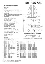
Been lucky enough to get myself a pair of slightly battered and war torn 662's from a friend. I've recapped and rewired Wharefedales in the past and have a feeling I'll need to do the same to these given their age. They were used by my pal in his recording studio and he blew the tweeters on more than one occasion. Having got them up and running - one tweeter didn't work - so swapped them over and found it's an internal fault not the tweeter itself. I notice the schematics posted here don't have any crossover info for the tweeter - I've not taken the units fully apart yet but wondered if anyone knows where the tweeters lie within the schematics - I'm assuming they'll be the treble ? As of the 4 speakers 2 must be bass./. thanks in advance.
Been lucky enough to get myself a pair of slightly battered and war torn 662's from a friend. I've recapped and rewired Wharefedales in the past and have a feeling I'll need to do the same to these given their age. They were used by my pal in his recording studio and he blew the tweeters on more than one occasion. Having got them up and running - one tweeter didn't work - so swapped them over and found it's an internal fault not the tweeter itself. I notice the schematics posted here don't have any crossover info for the tweeter - I've not taken the units fully apart yet but wondered if anyone knows where the tweeters lie within the schematics - I'm assuming they'll be the treble ? As of the 4 speakers 2 must be bass./. thanks in advance.
wondered if anyone knows where the tweeters lie within the schematics - I'm assuming they'll be the treble ?
Yes, the tweeter is the driver in the treble section.
As of the 4 speakers 2 must be bass.
EDIT: There is one bass driver, a midrange driver and a treble driver in each enclosure. The bottom unit as an ABR (auxiliary bass radiator).
Last edited:
If you have a multimeter, the tweeter is easy to check. Unscrew the 3 screws, and unplug the wire that are attached to the terminals. Just measure the DC resistance between the two terminals. If you have something like 7 Ohms or more this is okay. If it says OL, the wire in the coil is broken somewhere.
As for the replacement, you can just replace the diaphragm (see https://www.ebay.ca/itm/321962540376). I just replaced one in a Ditton 22 (HF1001 tweeter). Notice that the replacement may not have the same impedance so there is a bit of adjustment to do.
You want to do this in both tweeters if you want them to sound the same.
- Home
- Loudspeakers
- Multi-Way
- Celestion Ditton 662 - Capacitors replacement question