Re: mods for sba
Hi sba,
it seemed to me to be "an insightful and clever solution" when I thought of it more than 15 years ago and tried it then,
and it worked well enough within its limitations, thus I continue to use it when appropriate !
I am not surprised at the "significant amount of distortion" you found from the Behringer tube-pre,
because that product was basically intended to be an effect-producing device, and not a neutral pre-amp.
It is possible to design and manufacture a very low distortion valve/tube pre-amp, but it would not sell for that low price !
I hope the Rolls MP13 is sufficiently better -{I have not had time to research it}.
Distortion in the Behringer would have added Harmonics to the measurements, thus the errors would be in the higher frequencies of the Frequency Response plots, hence better would be to measure again via your new pre-amp.
For future Measurement:- better is to not apply Eighth-octave smoothing.
Twelfth-octave, at least, is more useful,
but really one needs Twenty-fourth octave to allow for Music notes' pitches and the intermediate spaces,
despite what Acousticians may state, because Acousticians are trained in measurement of Noise levels, not in Music measurement.
Stay with un-smoothed for the raw measurement procedure if possible though,
and look at 1/12 or 1/24 applied later to compare.
I do not know what Vertical Axis height Celestion used when measuring that Plot, though I think it was likely On-Axis to the mid-dome.
That plot shows the various anomalies present in the MD and HF domes that are also in your plots, thus likely yours are close to correct,
and allowing for Sample Variations, which you have found also, though some such in yours will be age-related deterioration caused.
Remember also, the reflection of sound from the top-lip of the enclosure will have caused some of the ripples in the plot,
and also in yours unless you have installed a suitable sound absorbing material there.
***************
Hah, I had picked the wrong MD to identify with the 2010 Freq. Resp./Distortion plot, but no worry - the remainder of what I posted still applies,
AND now the .34mH inductor will cause the Purple MD to closer match the Green MD in the region just above crossover after the 82 ohm or similar value resistor is paralleled with the Purple MD ... if you choose suitable tweeters.
I'll get to comments about your 8 samples of JBL tweeters before too long I hope ... don't sell any yet !
I think you may have disposed of one MF dome too soon, similar to one HF tweeter too soon, {though you don't really need the HF domes now}.
I would keep an eye out for MF domes at reasonable prices, perhaps in those B&O l'speakers, to hopefully get one which matches one of yours closer.
Note, from your MF Freq.Resp. plots, the MF version does extend fairly smoothly to 6kHz, thus likely why B&O chose to cross there,
and that allowed them an easier lower cross point of 600 Hz for less distortion in the low mids.
Your deteriorated Qms MD will likely have some-what extended life if you apply the 82 ohm parallel resistor to it,
but it probably won't survive as long as the other MD, thus I recommend you obtain another MD when one appears at a reasonable price.
I noticed that both MD samples were measured with the same Gating time, but saw the significantly different Gating times for each MF sample,
thus their lower-end Freq. Resp's may not be directly comperable in your plots, and not the lower-end distortion either if the different Gating times were applied to those also.
Try the 82 ohm or similar resistance with the faulty MD, and listen to the MD pair of 66s, then Post whatever degree of audibility here.
If you can hear an improvement, I'll Post more about parallel resistor options to further lower distortion, and to apply to the MF pair, if you want to proceed with such.
If you are buying Load Simulating resistors to substitute for tweeter and woofer to allow Mids' measurements with crossover connected,
then perhaps buy a suitable resistor to substitute for the mids also, so that you can measure the effects of the crossover on the woofer and tweeter separately.
A load Simulating resistor should be no lower in resistance than the DC Resistance of the driver, and not more than double that Resistance, and somewhere in between is usually best ... thus for those mid-domes I would use 7.5 ohm or 8.2 ohm.
10 watt will be OK if you test with low level signal, but there are wirewound resistors available from Madisound and Parts Express in 15; 20; 25 watts ratings, and there will be significant signal power sent via the crossover to the midrange if you are testing a woofer at medium signal level.
Alan,
That’s an insightful and clever solution !
And not reported ‘till now… While trying to solve that problem I found another. The mic’s phantom power supply / preamp (a Behringer tube mic100) was creating a significant amount of distortion. At least that’s what the audio analyser program indicated when I expanded a test beyond just the soundcard and included the cables, connectors, and finally the mic preamp itself into the in-out measuring loop.
After a lot of investigation I still don’t know the cause of the original problem, but a new soundcard installed on a different computer seems to work okay, so I‘ll use that setup. For the distortion problem I replaced the Behringer with a Rolls MP13 mic preamp, which also seems to work okay.
I don’t expect any major surprises from re-measuring, just perhaps a little more detail and accuracy. I also wonder how much the Behringer effected the distortion measurements. We’ll see! It was reassuring to see Celestion’s B&K plot.
****************************
Here’s some of the data you were wondering about. The colors here are synced to the original impedance plot, post #394.
I have two remaining md 500s (green & purple), and two mf 500s (green & orange). The other two mf 500s, (yellow & blue) were traded away.
Hi sba,
it seemed to me to be "an insightful and clever solution" when I thought of it more than 15 years ago and tried it then,
and it worked well enough within its limitations, thus I continue to use it when appropriate !
I am not surprised at the "significant amount of distortion" you found from the Behringer tube-pre,
because that product was basically intended to be an effect-producing device, and not a neutral pre-amp.
It is possible to design and manufacture a very low distortion valve/tube pre-amp, but it would not sell for that low price !
I hope the Rolls MP13 is sufficiently better -{I have not had time to research it}.
Distortion in the Behringer would have added Harmonics to the measurements, thus the errors would be in the higher frequencies of the Frequency Response plots, hence better would be to measure again via your new pre-amp.
For future Measurement:- better is to not apply Eighth-octave smoothing.
Twelfth-octave, at least, is more useful,
but really one needs Twenty-fourth octave to allow for Music notes' pitches and the intermediate spaces,
despite what Acousticians may state, because Acousticians are trained in measurement of Noise levels, not in Music measurement.
Stay with un-smoothed for the raw measurement procedure if possible though,
and look at 1/12 or 1/24 applied later to compare.
I do not know what Vertical Axis height Celestion used when measuring that Plot, though I think it was likely On-Axis to the mid-dome.
That plot shows the various anomalies present in the MD and HF domes that are also in your plots, thus likely yours are close to correct,
and allowing for Sample Variations, which you have found also, though some such in yours will be age-related deterioration caused.
Remember also, the reflection of sound from the top-lip of the enclosure will have caused some of the ripples in the plot,
and also in yours unless you have installed a suitable sound absorbing material there.
***************
Hah, I had picked the wrong MD to identify with the 2010 Freq. Resp./Distortion plot, but no worry - the remainder of what I posted still applies,
AND now the .34mH inductor will cause the Purple MD to closer match the Green MD in the region just above crossover after the 82 ohm or similar value resistor is paralleled with the Purple MD ... if you choose suitable tweeters.
I'll get to comments about your 8 samples of JBL tweeters before too long I hope ... don't sell any yet !
I think you may have disposed of one MF dome too soon, similar to one HF tweeter too soon, {though you don't really need the HF domes now}.
I would keep an eye out for MF domes at reasonable prices, perhaps in those B&O l'speakers, to hopefully get one which matches one of yours closer.
Note, from your MF Freq.Resp. plots, the MF version does extend fairly smoothly to 6kHz, thus likely why B&O chose to cross there,
and that allowed them an easier lower cross point of 600 Hz for less distortion in the low mids.
Your deteriorated Qms MD will likely have some-what extended life if you apply the 82 ohm parallel resistor to it,
but it probably won't survive as long as the other MD, thus I recommend you obtain another MD when one appears at a reasonable price.
I noticed that both MD samples were measured with the same Gating time, but saw the significantly different Gating times for each MF sample,
thus their lower-end Freq. Resp's may not be directly comperable in your plots, and not the lower-end distortion either if the different Gating times were applied to those also.
Try the 82 ohm or similar resistance with the faulty MD, and listen to the MD pair of 66s, then Post whatever degree of audibility here.
If you can hear an improvement, I'll Post more about parallel resistor options to further lower distortion, and to apply to the MF pair, if you want to proceed with such.
If you are buying Load Simulating resistors to substitute for tweeter and woofer to allow Mids' measurements with crossover connected,
then perhaps buy a suitable resistor to substitute for the mids also, so that you can measure the effects of the crossover on the woofer and tweeter separately.
A load Simulating resistor should be no lower in resistance than the DC Resistance of the driver, and not more than double that Resistance, and somewhere in between is usually best ... thus for those mid-domes I would use 7.5 ohm or 8.2 ohm.
10 watt will be OK if you test with low level signal, but there are wirewound resistors available from Madisound and Parts Express in 15; 20; 25 watts ratings, and there will be significant signal power sent via the crossover to the midrange if you are testing a woofer at medium signal level.
Last edited:
Finished the xover update . 82 ohm in parallel in the mid filter, and the 27 ohm in parallel in the tweet filter.. 0.5 r that was in series is gone. listened to mozart and am satisfied that all is as good as its going to be. toned upper mids down a bit, (I think)
No room left on PCB's for any more additions.
No room left on PCB's for any more additions.
Next step
Hi Doug,
Good so far ... I presume you have now heard the SEAS tweeters better ..?
With the 3.9uF at input and 6uF at output of the treble filter there will be loss of treble in the region just above the crossover point,
because Celestion designed that crossover to remove the excess in the lower treble region of the HF2000.
HF2000 does not have a flat frequency response - it had higher output at the low treble end of its pass-band,
and the 6uF cap in particular was chosen to substantially reduce that.
The SEAS you bought has Flat Response through all of its useable pass-band,
thus with those crossover caps there is too much treble removed from the low end.
Ideally both caps should be changed, but you may be lucky and like the sound sufficiently with only one cap changed,
AND there is an experiment you can try before you buy anything:-
Do you still have the old treble capacitors which you removed when you installed the ClarityCaps ?
If yes, then which type are they:
- the very old type - black cylinder 2uF ?
- the intermediate period type - pale bluish-green 1.5uF and 1uF caps in Parallel connected bundles ?
- the final period type -olive green caps in 0.68uF + 3.3uF and 1.5uF + 4.7uF ?
I can describe how you can connect some of these to try restoring the lower treble balance to hear,
before you decide whether to buy another new capacitor in Parallel with the 6uF ClarityCap at output,
thus, what do you still have ... or any other capacitors ?
Last edited:
gone too soon
Hi Doug,
well those olive green caps are not truely dinosaurs, because being a plastic film type they have a very long life
-{unless overdriven, and that would have been unlikely in a 66 treble filter}.
Their only fault is their mediocre sound, but they would have sufficed for an experiment.
I keep all old parts that are still useable, even if only for less critical applications.
Do you have two 10uF plastic film capacitors of any type ? ,
or in any value near to 10uF, or four of 4.7 or 5.6uF ?
Polar or Bi-Polar ?
These Bennic electros ...
do you mean Polar, being they have + marked at one end, or at one lead's junction, and perhaps - marked at the other ?
... or, do you mean Bi-Polar, -{as are used in loudspeaker crossovers and some electronics' applications}- ?
Also, what are the uF values of these ?
These Bennic electros ...
do you mean Polar, being they have + marked at one end, or at one lead's junction, and perhaps - marked at the other ?
... or, do you mean Bi-Polar, -{as are used in loudspeaker crossovers and some electronics' applications}- ?
Also, what are the uF values of these ?
Last edited:
polar plus/minus 3 of 3.3uf 1 of4.7 2 of 1.0 uf some are 50 & some are 100 volt suspect these NOT suitable for use in xover?
alternates for output capacitor
Hi Doug,
no, none of those will be suitable, because as +/- Polar there would have to be 2 connected in Series as: +[]- <--> -[]+ to make a Bipolar cap,
and with the low values you have there is not sufficient to make approximately a 10uF cap,
for which using Polars would require: +[22uf]-<-->-[22uF]+ in Series = 11uF.
The output capacitor will need to be about 10uF or a little larger for the low treble to be raised to cross smoothly to the upper mids.
With your particular hearing predicament you can keep the 3.9uF as the input cap to the treble filter now that you have BOTH resistors installed in the crossover {27 ohm and 82 ohm}.
With that 3.9uF and the .14mH inductor, and about 10uF as the output cap of the treble filter, the treble will increase in output as frequency increases,
that is: there should be approximately equal treble and upper midrange output around the crossover point, and a little more treble output in the 10kHz <--> 16kHz region, which I think is likely where you are now not hearing well, thus this should help.
You can do either of 3 things:
(1) - connect either a 3.9uF or 4.7uF PX series ClarityCap in Parallel with the existing 6uF ClarityCap there.
Because all these caps are the same width of internal foil, there should be no distortion of the transient response with Parallel connection there.
{I would choose the 4.7uF option, if I did this, for 6uF + 4.7uF = 10.7uF total.}
or (2) - remove the 6uF ClarityCap, and install a 10uF PX ClarityCap in its place.
This will be neater fit on the circuit board, and being a single cap instead of a parallel pair it MIGHT result in clearer treble,
because when using two caps in Parallel for High Treble frequencies the quality of the solder joints, and how the leads from both are joined can affect the sound.
The leads, if using 2 caps in Parallel, should not be twisted together along a length, but only touch at a single point at each end.
Given the small price difference between a new 10uF and a new 4.7uF, I think it better to buy the 10uF, unless you are very confident of what you are doing.
or (3) - if you don't want to risk $6.70 + $6.70 = $13.40 for two PX 10uF caps,
then also from Madisound:
look in their "Surplus Caps" and see: 10.0 mfd Polypropylene Cap 10MFDP/TYEE for $0.60 each.
These are USA made from TYEE, and are 100 volt and smaller size than the PX cap.
Part number is FMPP106K2A.
They are +/- 10% tolerance, thus you might get 9uF or 11uF at worst, but probably will be closer to the middle than that.
I doubt their sound will be as good as the ClarityCap, but I list it for if you want to experiment without spending larger money.
For your not needed 6uF caps, keep for future project, or put on ebay.
6uF is not a common value, and ClarityCap is very good quality, thus you may get a local buyer,
but I would keep them for possible future use.
***************
Note to other readers:
the above is for moermusic's specific circumstance.
I do not recommend this for general substitution of caps for the SEAS H737 tweeter,
unless you have the MD version of the mid-dome and will install the 82 ohm parallel resistor there,
and your hearing is failing for the highest treble frequencies.
For non-failing high treble hearing, and if you mid-domes are the MF version,
then when modifying for the SEAS tweeter both caps should be changed in the treble filter to 3.6uF and 11uF,
and using one of the Resistors' options I previously posted to reduce the SEAS's impedance to work with the .14mH inductor.
Last edited:
correction and addition
Spelling mistake in last paragraph above, and my Edit time has expired, thus it should be:
"if your mid-domes are the MF version".
The resistors to use as L-Pad around the SEAS tweeter are in Post #592 on Page 60,
and are 15 ohms Parallel + 1 ohm Series for about -1.6dB attenuation, which should result in flat response treble above the crossover point.
I have calculated resistors for less attenuation.
If anyone thinks they should use less, then Post here, and I will list whatever.
Last edited:
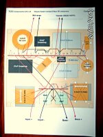
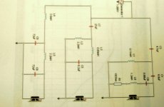
Design for new crossover matched to the SEAS 19TFF1 Tweeter
Please find attached two diagrams showing the proposed new crossovers for my Celestion 66's
Regards
Wayne
Please find attached two diagrams showing the proposed new crossovers for my Celestion 66's
Regards
Wayne
Attachments
Last edited:
Not this way for 66 sound !
Hi Wayne,
how/where/why did you arrive at that combination of components for a Celestion 66 crossover ?
(1a) - this will NOT give a clean modern version of the Ditton 66 sound,
because of the significant changes to the circuit, especially those to the low-pass filter section of the midrange circuit.
(1b) - why have you proposed that change to that part of the filter ?
(2) - it will sound excessive and forward in the midrange, because there are no attenuating resistors in what is a very Resonant circuit there.
(3) - the mid-dome may be damaged, or at least have its life reduced faster over time when the speakers are played loud, because of the 27uF capacitor.
Despite there being 30uF in the first version of the Ditton 66, Celestion reduced that to 24uF for good reason - to not permit excess low mids to drive the mid-dome.
(4a) - it will sound compressed and weak in the bass when driven hard, because of those cored inductors you have indicated.
Why are you changing from the original air-core inductors ?
(4b) - are those small-drawn caps in the bass filter plastic film or electrolytic ?
(5) - tweeter response is hard to predict straight away, but I'll study the circuit and reply further when I've evaluated the treble filter.
(6) - are those horizontally placed L1/.11mH and L3/.8mH inductors also solid-core of some type ? ...
and if so, why ?
(7) - it is a waste of money to buy the expensive Jantzen "Silver" caps if they are put into a circuit which is not optimised for balanced coherent sound.
Expensive capacitors cannot improve a flawed circuit design.
You can of course buy the components, and build this crossover - that is your right, and perhaps you will like it, but many have gone down similar paths and regretted it.
It looks very unbalanced to me, thus I'm interested to hear your reasons for proposing it ..?
Last edited:
Crossover Design
Please see Attachment.
Hi Wayne,
It looks very unbalanced to me, thus I'm interested to hear your reasons for proposing it ..?
Please see Attachment.
Attachments
Last edited:
Ask these things:
Hi Wayne,
very interesting, but the provided explanations omit some relevant matters,
especially about the Bass performance !
... however, before we get to that, I recommend you ask your circuit designer the following:
(1) - why is the C9 - L8 - R1 network in Parallel with the SEAS tweeter tuned to 5571 Hz ?
I would have thought it should be tuned to the tweeter's Fs, which is about 1600 Hz ... for which C9 would be about 8.2uF.
Perhaps there is an error there ..?
(2) - regardless whether the C9/L8/R1 network is correct or not, L1 is a very low value, and in combination with C3 and C1 will cause a lot of loss around the 5kHz region.
Why has that been done ?
(3) - despite the mention of Impedance Correction for the MD500, there is not any impedance correction circuit included for it, and especially not at the low frequency end where such could be most beneficial.
Why is it not included ?
(4) - the annomolies in the upper midrange Frequency Response of the MD500s - are these YOUR samples of MD500s, or other samples ?
As sba showed with his measurements, these old mid-domes do have annomolies, AND those vary between samples, thus whose Samples are shown in your measurements ?
(5) - in the midrange filter, L3 and C5 will cause substantial loss of output in the region just below 5kHz, thus when combined with the seeming large loss in the same area of the frequency spectrum caused by L1/C3/C5 in the treble filter, I think it likely there will be a hole in the frequency response there - a very audible one.
Perhaps there is an error in the calculations, or in the printed results - ask that to be checked ..?
(6) - the Resistors I recommended are NOT there to degrade the performance of the new capacitors {to make them sound like old capacitors},
they are there to keep the midrange in coherent balance with the treble and bass that is audible in this loudspeaker.
The 66 is a Balance of Compromises, and some of that I explained in various places during this Thread.
All loudspeakers require a Balance of Compromises, and if you want to update the sound using the old ABRs and woofers and mid-domes you will have to use another type of Balance of Compromises , otherwise some parts of the frequency spectrum will not be coherently in time with others when music is played ,{as distinct from steady state test tones}, - in other words, it can sound like a wobbly mess.
Enquire Points (1) <---> (5) inclusive first, and Post the replies, and then I will discuss the Bass issues ... if there seems to be any sense in proceeding with this design.
Last edited:
New crossover design
Hi Alan,
The crossover configuration is optimum for the actual drivers in the baffle at 2m on and off axis.
Some adjustment to balance may be required due to the reflective characteristics of my living room, speaker location and my personal preference. So once I have listened to the result I can then make a judgment and changes can be made.
Regarding the mid-range damage due to the change of C7 from 24uF to 27uF – this will not cause damage to the mid-range driver. Calculating the difference in effective attenuation at the lower crossover frequency (500Hz) between the two capacitor values give a 0.54dB difference - this is barely audible at this frequency (about 1dB is audible) and will increase the mid-range diaphragm excursion only slightly i.e. about equivalent to increasing the volume on my amplifier by about the same amount. 27uF is used because it gives a flatter response anecholically.
I would be interested in your views regarding the bass section.
Cheers
Wayne
Hi Wayne,
Enquire Points (1) <---> (5) inclusive first, and Post the replies, and then I will discuss the Bass issues ... if there seems to be any sense in proceeding with this design.
Hi Alan,
The crossover configuration is optimum for the actual drivers in the baffle at 2m on and off axis.
Some adjustment to balance may be required due to the reflective characteristics of my living room, speaker location and my personal preference. So once I have listened to the result I can then make a judgment and changes can be made.
Regarding the mid-range damage due to the change of C7 from 24uF to 27uF – this will not cause damage to the mid-range driver. Calculating the difference in effective attenuation at the lower crossover frequency (500Hz) between the two capacitor values give a 0.54dB difference - this is barely audible at this frequency (about 1dB is audible) and will increase the mid-range diaphragm excursion only slightly i.e. about equivalent to increasing the volume on my amplifier by about the same amount. 27uF is used because it gives a flatter response anecholically.
I would be interested in your views regarding the bass section.
Cheers
Wayne
Last edited:
About the midrange drivers:
Hi Wayne,
are the plots' measurements of YOUR particular MD500s, or from other samples ?
Hi Wayne,
are the plots' measurements of YOUR particular MD500s, or from other samples ?
Hi Wayne,
are the plots' measurements of YOUR particular MD500s, or from other samples ?
Hi Alan,
They are mine.
Regards
Wayne
Hi Alan,
I know that somewhere amongst these 'threads' there is something about using some kind of sound dampening material under the lip of the top of the Cellestion 66's. Can you remember what the outcome was to all the various ideas put forward?
Best Regards
Wayne
I know that somewhere amongst these 'threads' there is something about using some kind of sound dampening material under the lip of the top of the Cellestion 66's. Can you remember what the outcome was to all the various ideas put forward?
Best Regards
Wayne
Here are some “corrected” measurements of an MF driver, an MD driver, a 66 woofer , and a 66 system (with the MD500 & hf2000).
Before I could get to the HF2000, or to Alan’s mid-dome experiment, or to other items on my list, I was told to pack up and put away my measuring toys. So those will have to wait for another time.
I made a few test measurements with both Holm and REW in order to do a cross check (which turned out fine), and then decided to proceed with REW because of its ability to plot polars. With REW, 1/24 smoothing was about as high in detail as I could tolerate on the crowded plots….so all of the plots that are posted here have 1/24 smoothing. I don’t have an SPL meter, so the SPL is only relative within a particular plot. The measurement distance was one meter. The individual drivers were measured both solo and connected to the crossover network Dummy loads were 6r on the woofer circuit, 8r on the mid, and 5.6r on the high.


- Home
- Loudspeakers
- Multi-Way
- Celestion 66 needs mid-range