CAPACITORS for each 66 version, continued ...
This is only necessary for capacitors connected in Parallel.
For capacitors connected in Series, one can use different Brands, and/or voltage ratings, with no problems with Transient Response - if the caps are well made.
sba mentioned using differnt caps for tonal shading, or some similar phrase to that, he had read about.
Well, here is a place to try such if one wants to - use one good quality brand for the 6uF or 6.2uF position and a different good quality brand for the 4uF position.
This may be of use to 66 owners who want to use single caps in each location and not parallel bunches, as some brands have a 6.2uF, and at least one has a 6uF.
I'll Post more about those in a later Post.
____________________________________________________
sorry, little time today, I'll have to leave the Mid-range Filter till next time .
24uF or 28uF or 30uF, and other ideas, etc ...
alan-1-b said:,
AND, use all of the same Brand , type and Voltage rating.
This is only necessary for capacitors connected in Parallel.
For capacitors connected in Series, one can use different Brands, and/or voltage ratings, with no problems with Transient Response - if the caps are well made.
sba mentioned using differnt caps for tonal shading, or some similar phrase to that, he had read about.
Well, here is a place to try such if one wants to - use one good quality brand for the 6uF or 6.2uF position and a different good quality brand for the 4uF position.
This may be of use to 66 owners who want to use single caps in each location and not parallel bunches, as some brands have a 6.2uF, and at least one has a 6uF.
I'll Post more about those in a later Post.
____________________________________________________
sorry, little time today, I'll have to leave the Mid-range Filter till next time .
24uF or 28uF or 30uF, and other ideas, etc ...
Before Christmas I posted I had acquired a pair of eBay blackie 66s. These duly arrived in full working order, with all drivers working and no unpleasant noises. I have spent a month listening to them with various different amplifiers and ***** them as follows. They are rather poorly balanced and somewhat lacking in high frequencies with a somewhat overpowering mid range. The bass is firm when driven by the right amplifier - my 211, but hopelessly flabby and overpowering when driven by parallel 300b amps. I tried a quad 606 but the 211se gets the best out of them. Overall, pretty good for a 30 odd year old speaker. The crossovers have had a couple of caps changed (well done too!) and utilised 28uf for the mid. 2 off 12uf an a 4uf all in parallel.
Anyway, after a months assessment I decided it was time to measure the crossover components and as expected from the contents of this thread, all the caps are way out of spec. Most measure way over so I suspect they leak heavily. I replaced the worst with assorted caps from my parts bin which immediately improved matters. As a result I have ordered new polypropylenes. I decided to use close tolerance 1% Daytons which have the advantage of being available in the correct values without mixing different values. I've used them before and they sounded OK to my rather poor ears. They are cheap too. I'll report back when they arrive. I have read this entire thread and found it very helpful.
Thanks to all.
I have high hopes for these speakers. The initial sound with jaded crossovers shows they have real promise.
User Reports are most helpful !
Hi Phil,
the Dayton caps should be fine - I have heard the basic Bennic capacitors, which Daytons are, many times.
Yes, the advantage of the +/- 1% tolerance.
30uF // 40uF summing to 70uF is close enough for the 72uF locations, in particular for the cap closed electrically to the woofer.
Three of 25uF in parallel summing to 75uF would be fine in the other 72uF location, if you want to compensate for a little less in one part of the filter by using a little more in another part this is the way to do it with absolutely minimal detuning of the filter.
Parts Express don't have suitable size resistors for the ESR simulating resistors I have Posted about.
I hope to get time soon to fully list the resistors, but in the interim time, being as it seems you have ordered the caps and are keen to audition, you may as well install the caps and listen.
The upper mids will probably be a little too prominent without ESR simulating resistors, and you may hear some additional annoying resonances which you would not have heard with the old caps, which the resistors will eliminate, or at least reduce.
Yes do report your auditioning results, as this will be helpful for owners to consider when fine-tuning their 66s
As for your self-descriptive comment - "my rather poor ears" - I do not believe a word of it !
- that from a man who owns 211SE and 300B amplifiers ...
I had hoped to have time to earlier comment on your first Post.
As it seems you are able to wind transformers I should have got in earlier with my recommendation you rewind your Output Transformers with about 10% of their Primary separate, and connect this section in the Cathode circuit - that is from 211 cathode through transformer section to ground.
The winding is to replace the cathode resistor which is then ommitted, as also is ommitted any cathode capacitor.
You would need to select a suitable tapping point from the Power Supply and make a Bias supply circuit to supply the negative voltage to the 211's grid, which was previously Auto-supplied as result of the cathode resistor. This is not difficult to do.
Audible advantages of this circuit include better control of bass response, particually with speakers of the 66 type with significant resistance in their series connected bass filter inductors and their ABR.
Also, a good quality transformer winding gives better sound quality over the whole range than a by-pass capacitor can here.
This type of circuit - Cathode coupled - was not known in the era of Single Ended amplifiers, thus why it is not used with them now, because most enthusiasts are not technically minded, but simply want the magic of the old SE technology.
I do not know who first though of cathode connected transformer windings, but it is used in at least one old Dynaco amp, and in the original Quad II - and despite the less than optimum bass quality of that amp, such is not the fault of cathode coupling into the O/P transformer.
A modern well designed and well manufactured transformer with separate cathode winding can produce very good bass response.
Audio Note UK's transformer designer does know how to do it.
The Company doesn't manufacture such amps simply because not sufficient people have heard such to ask for them in quantity.
Yes, such can be applied to a 300B amplifier.
Yes, such can be applied to Single Ended amplifiers, not only to Push/Pulls.
Hi Phil,
the Dayton caps should be fine - I have heard the basic Bennic capacitors, which Daytons are, many times.
Yes, the advantage of the +/- 1% tolerance.
30uF // 40uF summing to 70uF is close enough for the 72uF locations, in particular for the cap closed electrically to the woofer.
Three of 25uF in parallel summing to 75uF would be fine in the other 72uF location, if you want to compensate for a little less in one part of the filter by using a little more in another part this is the way to do it with absolutely minimal detuning of the filter.
Parts Express don't have suitable size resistors for the ESR simulating resistors I have Posted about.
I hope to get time soon to fully list the resistors, but in the interim time, being as it seems you have ordered the caps and are keen to audition, you may as well install the caps and listen.
The upper mids will probably be a little too prominent without ESR simulating resistors, and you may hear some additional annoying resonances which you would not have heard with the old caps, which the resistors will eliminate, or at least reduce.
Yes do report your auditioning results, as this will be helpful for owners to consider when fine-tuning their 66s
As for your self-descriptive comment - "my rather poor ears" - I do not believe a word of it !
- that from a man who owns 211SE and 300B amplifiers ...
PhilPrice said:
I have a selection of amps to use with them but plan to use them with a 211 valve amp I built a few years ago based on Audio Note circuitry - except I just plugged it in and it fried the mains transformer. Bummer. That'll keep me busy rewinding that. It provides awesome bass when it works so I'm looking forward to trying it with the 66s.
Anyone use valves to drive 66s?
I had hoped to have time to earlier comment on your first Post.
As it seems you are able to wind transformers I should have got in earlier with my recommendation you rewind your Output Transformers with about 10% of their Primary separate, and connect this section in the Cathode circuit - that is from 211 cathode through transformer section to ground.
The winding is to replace the cathode resistor which is then ommitted, as also is ommitted any cathode capacitor.
You would need to select a suitable tapping point from the Power Supply and make a Bias supply circuit to supply the negative voltage to the 211's grid, which was previously Auto-supplied as result of the cathode resistor. This is not difficult to do.
Audible advantages of this circuit include better control of bass response, particually with speakers of the 66 type with significant resistance in their series connected bass filter inductors and their ABR.
Also, a good quality transformer winding gives better sound quality over the whole range than a by-pass capacitor can here.
This type of circuit - Cathode coupled - was not known in the era of Single Ended amplifiers, thus why it is not used with them now, because most enthusiasts are not technically minded, but simply want the magic of the old SE technology.
I do not know who first though of cathode connected transformer windings, but it is used in at least one old Dynaco amp, and in the original Quad II - and despite the less than optimum bass quality of that amp, such is not the fault of cathode coupling into the O/P transformer.
A modern well designed and well manufactured transformer with separate cathode winding can produce very good bass response.
Audio Note UK's transformer designer does know how to do it.
The Company doesn't manufacture such amps simply because not sufficient people have heard such to ask for them in quantity.
Yes, such can be applied to a 300B amplifier.
Yes, such can be applied to Single Ended amplifiers, not only to Push/Pulls.
Hello Alan,
The Daytons arrived this morning and I have installed them. the values chosen were 3uf *2, 4uf ,25uf - based on the fact it had 28 before. For the 72uf I decided to order 75uf caps with 10% tolerance and make the best of the four that arrived. As it happens they all measure between 72.5 and 73.5 so thats close enough. Initial audition suggests a great improvement - much more than I was expecting. It seems to have toned town the strident mid range and greatly sharpened the high frequencies. As high as I can hear anyway which is about 13kHz. I will wait a while before I decide to install resistors to get a true picture over a large range of material.
I have not come across cathode coupled windings before and I found it most interesting. The 211se has no cathode resistors or caps, the cathode being strapped to ground, but the 300b does have cathode bias, which probably explains what I heard. I had assumed the problem with the 300b amps was poor impedance matching as they are very good with other speakers. The 300b amps will probably end up on eBay.
Getting off topic a bit but the 211 mains transformer always ran far too hot so I have rewound it without the 211 heaters which now run from their own transformer. It has solved the problem. I built the 211 in the early 90s based on the ongaku circuit using AudioNote UK transformers. It sounds OK to me.
Back on topic. As I have typed this I have been listening to a Tracy Chapman disc. It really is quite impressive now. The bass has the sort of feel I last heard from a big Krell through some Wilsons. Not bad for £400 speakers.
Thank you very much for you input.
I'll try and post some pictures here later and report back after I've had a proper listen.
Phil
A few discs on and I am truly stunned at what these are capable of.
The Daytons.
The system.
There are a few concessions toWAF in this room and no, that's not my listening chair.
Phil
The Daytons.
An externally hosted image should be here but it was not working when we last tested it.
The system.
An externally hosted image should be here but it was not working when we last tested it.
An externally hosted image should be here but it was not working when we last tested it.
There are a few concessions toWAF in this room and no, that's not my listening chair.
Phil
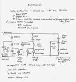
Tweeter Polarity in Ditton 44
Very interesting harnfield ... 44 versus 66 tweeter connections.
As an initial suggestion, try changing the Polarity connections to the tweeters in your 66s, that is from the current Reverse to positive tweeter terminal to the caps' line, and negative tweeter terminal to earth.
Any preference of one way to the other ?
What do you like or don't you like about the change ?
I won't load your anticipations by saying what you might hear, other than to try a somewhat different listening height, if comfortable to do so, or if you have short sturdy speaker stands to try.
Phil
I'll type some comments inside the Quote Box, following each of your points, ---->
Readers can easily see the relative sizes of the Dayton and Bennic caps from Phil's photo, and judge whether a 75uF will fit on their x-over board between the inductors.
I'll type some comments inside the Quote Box, following each of your points, ---->
PhilPrice said:
The Daytons arrived this morning and I have installed them. the values chosen were 3uf *2, 4uf ,25uf - based on the fact it had 28 before. For the 72uf I decided to order 75uf caps with 10% tolerance and make the best of the four that arrived. As it happens they all measure between 72.5 and 73.5 so thats close enough.
----> Well you are lucky, though I think with the 75uF caps they may be close to the nominal spec. because few, if any, other Companies will be buying 5% tolerance 75uF caps, thus the best within the 10% spec. are also sold at the cheaper price, and you got some !
For the smaller cap values I'll bet all the 10% Bennics are outside +/- 5%, because the within 5% ones will have been selected and sold to re-sellers of 5% Bennics, {there are some}, and the very closest to nominal value will likely have been selected and potted in white and sold to Dayton for their 1% caps.
____________________________________________________
Initial audition suggests a great improvement - much more than I was expecting. It seems to have toned town the strident mid range and greatly sharpened the high frequencies. As high as I can hear anyway which is about 13kHz.
----> That's because you have a Nylon strung guitar from which there will likely be no Harmonics above about 13kHz and you have conditioned your hearing as result of playing it !
{heh heh}
Interesting, because from what harnfield has reported it seems the Blackie era HF2000s may be strong output between 5kHz {with this x-over} and approx. 10kHz and then slope down a little in frequency.
They probably still extend to 20kHz, but at -6dB with reference to their below 10kHz level.
I am guessing, but I think HF2000 may have been intended for use as high treble specifically, with a x-over designed to roll it in above 13kHz where the HF1300 starts to drop off significantly.
That is, HF2000 similar in application to the old Coles Supertweeter.
I see Coles have a CE 4001 supertweeter now, and I wonder what the shape of its Frequency Response plot is ...
hopefully harnfield has been able to get a Plot from Coles, and can tell us, or Post it in the thread ...
Any luck harnfield ?
Thus Phil, what is your Reference for thinking you can only hear to about 13kHz ?
____________________________________________________
I will wait a while before I decide to install resistors to get a true picture over a large range of material.
----> I should stop commenting on other peoples' Posts so that I have time to Post specifics of the ESR simulating resistors ...
but certainly it is a good opportunity to hear the drivers terminated somewhat differntly to how they were in the originals {when those old caps were new}.
____________________________________________________
I have not come across cathode coupled windings before and I found it most interesting. The 211se has no cathode resistors or caps, the cathode being strapped to ground,
----> Which pin is strapped to ground ?
and, I suppose you are running DC filament voltage ..?
____________________________________________________
but the 300b does have cathode bias, which probably explains what I heard. I had assumed the problem with the 300b amps was poor impedance matching as they are very good with other speakers.
----> How a Cathode Biased amp sounds does vary with speaker quite a lot, and particually with magnitude of Impedance variations, greater or lesser in some speakers than in others.
____________________________________________________
The 300b amps will probably end up on eBay.
----> well, you could pay Audio Note to wind Cathode tapped transformers for you, suited to 300Bs, or sell them and save for an amp with cleverly designed and manufactured windings in output transformer, such as the E.A.R and Yoshino amps in the UK, or the McIntosh in the USA, though all these are expensive !
____________________________________________________
Getting off topic a bit but the 211 mains transformer always ran far too hot so I have rewound it without the 211 heaters which now run from their own transformer.
----> indeed I would expect this given the amount of current a 211 filament draws, and at higher voltage than most valves,
and pulling that large supply from a different transformer should improve the sound of the amp, as the main transformer has only to contend with audio power supply, {and you seem to have heard this},
but do ensure your filament transformer always turns on exactly with, or before, your mains transformer, or you'll have short life 211s ... {I think you may know this, but experimenters reading this may not}.
____________________________________________________
Back on topic. As I have typed this I have been listening to a Tracy Chapman disc. It really is quite impressive now. The bass has the sort of feel I last heard from a big Krell through some Wilsons. Not bad for £400 speakers.
----> not surprising, the bass, given where you have placed the speakers, but hey if you like it they will give it !
Good photos !
and your 211 amp, is it two amplifiers in a single chassis, or is it a Parallel SE, and you have another one out of sight ?
Alan
____________________________________________________
Phil
Readers can easily see the relative sizes of the Dayton and Bennic caps from Phil's photo, and judge whether a 75uF will fit on their x-over board between the inductors.
Thanks for that Alan.
Hearing? I can detect a 13khz sinewave tone but by 14khz I hear nothing. My son hears it ok. Occupational damage and advancing age I suspect. It doesn't decrease my enjoyment of music.
Which pin of the 211 is grounded? Actually neither so not strictly true that there are no cathode resistors. It was AC heated but I couldnt get rid of the hum with the usual pot/resistor arrangement so I made it DC with 20,000uf of smoothing per 211. It still hummed a bit with one end of the filament grounded so I reverted to using the pot/resistors to virtually ground the middle of the filament. It is now hum free. I believe this is the arrangement used on later Kondo amps. Interestingly a few of the other changes I made early on found their way onto later Kondo schematics.
I decided to put the esr simulating resistors in as you were correct about the upper mid frequencies - especially with speech. As expected, it improved matters. I think the 66s are now performing very well.
I'm happy with them.
Thanks.
Phil
Alan,
I just saw your edit. The 75ufs will not fit between the inductors. There is enough room to fit them between the inductors and magnets supported by foam over the inductors and cable ties to holes in the tag board.
I just saw your edit. The 75ufs will not fit between the inductors. There is enough room to fit them between the inductors and magnets supported by foam over the inductors and cable ties to holes in the tag board.
You edited again!
I can't edit my posts yet presumably as a new user so here's another.
My 211 is a stereo unit - My interpretation of Kondo's Ongagu. I listened to one in the early 90s played through a pair of Spendors I think, and it was a revelation. When the schematic became available from AudioNote UK I decided to make a copy. It was my second amp after the 300b kit. The case was scratch built from Dural and English yew as these were materials I had to hand. The only plan was a picture on the front of Positive Feedback magazine and the schematic. Initially the component choice was based in cost but it now has Black Gates, tantalum resistors, NO chinese valves, silver wire and a few circuit tweaks. The OPTs are still copper. I dont know if its as good as a Kondo. Probably not. I havent heard a proper one since about 1993.
Way off topic.
Sorry.
Phil
Thanks Cal.
Great site.
There is so much information here. When I started this, before the internet, information and parts were so hard to find.
I'll detail the trials and tribulations of the Ongaku with some pictures in a more appropriate thread.
Phil
Great site.
There is so much information here. When I started this, before the internet, information and parts were so hard to find.
I'll detail the trials and tribulations of the Ongaku with some pictures in a more appropriate thread.
Phil
*
Hi all,
Thanks for the informative discussion on resistors. I needed some for my JBL project (a new crossover for a 10" three-way system) and ended up ordering Mills resistors from PartsConnexion in Canada (they have a large selection....both 5 and 12 watt versions). Parts Express, as Alan noted, has only a limited range of Mills resistors.
What's the summary then for the ESR compensating resistors for the 66 ?
All values at 5 watts...or ?
Is a single resistor okay with uneven-value // caps (e.g., 62 // 10 ) ?
1r5 in series with the woofer's proximal 72uf cap ?
1r2 in series with the woofer's distal 72uf cap ?
1r5 in series with the midrange 24uf cap ?
&
100r bridge across the tweeter (to counteract a 5k overlap)......Overlaps, Spikes, Dips.......I'm just thinking.....it would be nice to take actual driver measurements and then have graphical images of such phenomenon.........In the mean time, you pros are doing a darn good job using just your ears and experience.
The discussion about valve amps is most welcome and has made me nostalgic for my first HiFi back in the late 60's.....a Leak Point One amp/preamp, driving a single Altec 604-B. It sounded really good, but my friends, who had these colorful space-age looking stereos from Panasonic and others, were sort of puzzled by my 1940's system, which was usually quite dusty, required a warmup period, required frequent knob set-screw tightening, etc, Eventually I replaced it with a Marantz. I'm now driving my two pairs of 66's with a McIntosh 4100 receiver. It seems to do a good job and I like that it has a clipping indicator/protection circuit.
sba
okay, I just found some of my answers in post#183, which I just processed for the first time--
******************
" there will be an audible resonance generated by the 72uF cap in direct parallel with the woofer,
in fact 2 resonances in your situation of 2 very different capacitance values in parallel {very different charge/discharge cycles} compounded by their very different Pulse Rise Times {determined by their different lengths, the internal widths of their foils}.
Solutions :- an ESR simulating resistor in series with each cap.
1 ohm/5 watt non-inductive in series with the 4uF,
1 ohm/5 watt ** ** ** ** ** ** 62uF,
4 ohm/5 watt ** ** ** ** ** ** 10uF.
I will be posting more about this, and some related matters soon, as an ESR simulating resistor should be placed in series with the 24uF cap, and again in your case, 2 resistors. "
**********************
Alan, which 4uf cap location ?.....the one in the mid, or the treble, or both ?
So, then, keep the resistance the same in both 72uf locations ? That works out to be 0.8r in those locations !!
Perhaps I"ll put a single cap in the 24uf location....and in both treble locations.
can you wait a week ?
Hi sba,
sorry, I have very litle time right now ...
For your particular, and unusual, case -
for the 10uF woofer caps use a series resistor close in value to the DC resistance of the woofer, such as 4.3ohm {which at least one of the Mills' sellers has in 5 watt - either "Parts Connection" or the "Sonicap" direct sales mail-order site.
Significantly larger than woofer DCR will not acheive much good, thus 4.7 ohm maximum.
for the 62uF electrically closest to woofer use 1.5 ohm in series.
for the other 62uF use 1.2 ohm.
for the 4uF cap in parallel with the mids use 3.9 or 4 ohm in series.
5 watt for all these.
I have some ideas for resistors for your 10uF // 15uF mids' cap ,
but I don't have the notes I made about those with me.
If you want to change your mids' caps , I think buy some of those 9.1uF on-sale Solens and parallel to 27.3uF for your Blackie MF500s, and use parallel 12s or 24uF for your Woodie MD500s.
I'll explain all this in a Post when I have more time.
When do you want to start on this ?
For now, try 15uF // 15uF in your Blackies - alone , single pair of speakers' listening to hear how they sounded with 30uF originally, and with at least 1.5 ohm series resistor, 5 watt if you want to install now.
What combination of cap values did you use for the 6uF/6.2uF position to your tweeters - I can't see from the photo ?
I Posted a Correction to my Post #183 in Post #199,
and that covers some of what I've repeated here,
{I should have looked at it again first !} .
As you have a McIntosh amp {receiver} , I have an idea of an alternate way you can connect and place your 2 pairs of speakers to spread the sound around the room, etc , but this will take a long time explain , thus not now .
Alan,
Thanks.....There's no hurry....It will be a couple of months before I have time to continue on this project.
My plan is to move the crossovers to the outside, to re-lay the components for increased swappability, and to create additional distance between the coils......all while making it look half way decent. ( The JBL external crossover that I'm now working on will be the prototype.)
Anyway, I'll keep the // caps in the two 72uf locations and incorporate 5watt series
resistance there :
closest = 62uf + 1r5 // 10uf + 4r3
farthest = 62uf + 1r2 // 10uf + 4r3
All other locations will have SINGLE caps :
Treble = 3.9uf + ? -------- 6.2uf + ?
Mid = 3.9uf + 3r9 ------ 24uf * + ?
* Solen has 30ufs on sale for $ 5 (so, 30uf + 1r5 for experimentation on blackie's MF500 mid).
sba
Web-site down last week ?
Hi sba,
the web-site would not access on 2 successive days I tried a week ago - perhaps it was Down for ?
I have only very limited time for now, but as follows for your questions :-
Treble will not require ESR simulating resistors because the ESR of the Mylar caps in the Woodies is very low,
and the ESR of the PIO caps in the Blackies will have been quite low originally - much lower than any of the Elcaps - and not audibly significant.
Listen with the resistors in the other locations, and only if the Treble seems too much will a resistor be useful.
Possibly the treble will sound a little more Forward or Present than it did with the Mylar caps in your Woodies, but that is simply because Polypropylene caps render clearer sound.
Adding Series resistance of 0.5 or 0.47 {whichever is available and must be non-inductive in this application} would be the Maximum I would think necessary to blend the sound back in with the other drivers, BUT
this is not very likely because
harnfield has found that the upper treble was not sufficient, and only the lower treble was a little excessive with his Blackie era 66s after all new Solen caps.
We are working on this with another idea, thus wait for the results of that - he will report when done.
You must have a lot of disposable cash - surprises me because you bought resistors some not quite optimum values as at reduceed price, and now you plan to buy more which MAY not give the best results.
Really really really I recommend you disconnect some of your 15uF caps and use a pair for 30uF, plus a Series resistor of not less than 1.5ohm, and listen.
I think it quite likely that 30uF willl be a little too large there, and that about 27uF will give better results.
Remember Celestion changed to 28uF there, AND, as you found, B&O use a higher crossover frequency with those older model domes - MF500 ,
thus you may be wasting your money buying 30uF caps.
Experiment as above,
or if you want to buy, the try the 3 // 9.1uF for 27.3uF there, with a single Series 1.5ohm.
Use 1.5ohm minimum with 24uF in the Woodies.
From what harnfield has reported to me, less resistance will likely be too little.
" You must have a lot of disposable cash"
Ha! I just re-financed the house to get cash for my speaker projects. At this moment, the Wall Street geniuses are repackaging my sub-prime loan for you UK investors. Watch out!
Seriously though, I 'm content with 24uf in the mid......I mentioned the 30uf sale because of your suggesting trying something more than 24uf in that location in post # 257. Let's stick with a single 24uf cap there (& 1r5 or greater resistor). It's okay with me....you've demonstrated that single caps are a better choice....and they're easier to work with, too.
Yes, I know, I initially jumped the gun and didn't get the SINGLE caps that I should have.....but I'll correct that for the treble & mid locations.....and write off that first purchase as a learning experience on my first crossovers.
- Home
- Loudspeakers
- Multi-Way
- Celestion 66 needs mid-range