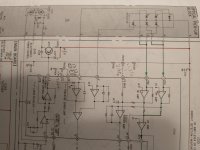
I'm trying to fix my loved Sony cdp-605es CD player and ran into problems. I have the service manual and have swapped out the laser. The player spins but won't read the TOC. The manual does not cover the focus error amp bias nor tracking error amp bias adjustment. These are two trim pots on the RF board (the 3rd is LD power which I set correctly).
Anybody have ideas on how to adjust these two? I tried the tracking error and gain adjustments on the main board per the manual but it didn't make much difference. I recorded the resistance of the error amp bias pots but wanted to know if there was any info on setting these before random adjustment.
Thanks to anybody who has ideas!
Hi pedrickj,
I haven't taken the time to look up the manual.
If your unit uses a KSS-210A / KSS-150A, did you remove the short on the head?
If it uses a KSS-240A, the replacement head could be bad. I've seen many of those. If the head was cheap, do not count on it!
If you bought a "substitute head", well good luck with that.
The player will work with the trimmer pots set to the original positions unless it is a really crappy head. So adjustments are NEVER TOUCHED during troubleshooting. Yet everyone always messes with the alignment first because they don't know any better. So, put each control to it's original position exactly. E-F Balance is very sensitive to it's alignment position.
You absolutely do require real test CDs and an oscilloscope to make any alignment to a CD player. You also need experience. For some procedures you require an oscillator, frequency counter and accurate AC voltmeter or in some cases a dual AC voltmeter. I have all these things - 'cause they are required. Believe it or not, a trained technician is always needed to repair anything almost properly. It isn't easy, but someone with skill makes it look that way, or YouTube stars aren't getting it right.
-Chris

Chris. thanks for getting back to me! This player uses the BU-1E optical block. The replacement laser came out of a hardly used cdk-006 juke box (these were in the Personics CD to cassette burners that flopped in the late 80's). That one uses the BU-1B which is very similar but not identical at that level. Many of the sub components are identical and have the same p/n.s. I swapped the flex board, linear magnet assy's, rails, and optical head. It was only a few screws and unplugging the flex board - really simple.Hi pedrickj,
I haven't taken the time to look up the manual.
If your unit uses a KSS-210A / KSS-150A, did you remove the short on the head?
If it uses a KSS-240A, the replacement head could be bad. I've seen many of those. If the head was cheap, do not count on it!
If you bought a "substitute head", well good luck with that.
The player will work with the trimmer pots set to the original positions unless it is a really crappy head. So adjustments are NEVER TOUCHED during troubleshooting. Yet everyone always messes with the alignment first because they don't know any better. So, put each control to it's original position exactly. E-F Balance is very sensitive to it's alignment position.
You absolutely do require real test CDs and an oscilloscope to make any alignment to a CD player. You also need experience. For some procedures you require an oscillator, frequency counter and accurate AC voltmeter or in some cases a dual AC voltmeter. I have all these things - 'cause they are required. Believe it or not, a trained technician is always needed to repair anything almost properly. It isn't easy, but someone with skill makes it look that way, or YouTube stars aren't getting it right.
-Chris
Since the juke box worked before there was to grounding solder blob to remove. I do have most of the test equipment needed - an analog 2 ch oscope, old heathkit frequency counter, antiststic workbench etc. I am a retired aerospace eng. so I should have the needed skills to attempt this transplant. I worked through the service manual and extrapolated to set the LD current based on the service manual of both these players. Neither one addresses the two pots on the RF board which set the op amp biases. Seems weird as there are access holes to adjust these two (plus LD power) while the unit is operating. The manual states how to adjust the focus/tracking gain which are separate adjustments on the main board. Seems like op amp error bias needs to set before the gain though.
The reason I suspect that those two error biases need adjusting is that the LD power written on the two optical blocks differed by quite a bit. The old one was supposed to be 63 mA and the "new" one was rated at 51 mA. I was thinking 23% difference might negate the "should generally be replaceable without pot adjust" advice I actually did see in some other thread here.
Anyway, glad to supply these additional details about my situation if it clarifies things. Thanks again! PS, I do not have the requisite YEDS-1 test disc you mentioned - hoping to get in the ball park with a standard CD if possible.
Hi pedrickj,
Perfect! Thank you.
Okay, the two numbers on the head are laser currents for a specified output level. This is to be measured and never, ever adjusted. You are allowed a 10% increase before the head is officially condemned as unusable. Those differences are expected. The lower current indicates a more efficient laser diode (and I prefer those). So install the head with the lowest percentage increase. That will be the better head of the two. If you don't have a laser power meter you cannot confirm output levels, but you can be pretty confident it's okay if Iop is within range.
There should be three offsets, some later machines use a servo (never as good as a careful setting). Most of what you need to do can be done by looking at the RF pattern (Eye pattern). Set your scope for 0.5 usec / div and 0.5 V/div, maybe 0.2 V/div, you may have to browse to find the RF test point if it isn't labeled. It is at the output of the RF amp (I to V converter). Tracking offset is typically setting 0 VDC at the tracking coil drive output, focus offset is similar at the focus coil drive output. E-F balance is critical, this adjustment can make the CD player not even read the TOC (Table of Contents). Find the slight dent in the rotation of that pot for a starting point. It should read at that point. Then carefully and slightly adjust that control for the best eye pattern. What I do is look at the RF envelop recovery from a scratch and adjust so the beam is on track. I use "Pierre Verany" disc #2 for this. It is a precise adjustment. Other methods involve turning off the tracking servo and adjusting the effective DC level of the resulting search waveform for zero, but it isn't nearly as close.
Tracking and focus gain adjustments are simply setting the gain at a point where the servo output has the lowest low frequency component (gain too low) and lowest HF component (Gain too high). Your scope is set to about 500msec on the corresponding servo output to the coil. This procedure differs from most manuals, but it works the best.
I have not had a chance to look at your manual, so some of the adjustments I referenced may not exist. If that is the case the adjustment is servo controlled. Don't worry about it.
Critical adjustment point, and this is mechanical. Turntable (disc table) height. This is another critical adjustment and needs to be very close to bang-on. Your manual should hopefully list this value, if not measure the jukebox unit. Tables can slip downwards on the shaft and cause bg tracking problems.
Let me know how things go please.
-Chris
Thanks - Hooked up the scope and did get an eye pattern. It seemed kind of unstable so after tweaking RV102 in the attached schematic, it got a little better as shown in the attached video. The blinking seems like an undesirable dropout - how stable should it be? Towards the end of the vid is a fuzzing blip where it must lose lock or something. That latter anomaly was reduced by the RV102 adjustment. The disc spins continuously and the TOC is still not read.Hi pedrickj,
Perfect! Thank you.
Okay, the two numbers on the head are laser currents for a specified output level. This is to be measured and never, ever adjusted. You are allowed a 10% increase before the head is officially condemned as unusable. Those differences are expected. The lower current indicates a more efficient laser diode (and I prefer those). So install the head with the lowest percentage increase. That will be the better head of the two. If you don't have a laser power meter you cannot confirm output levels, but you can be pretty confident it's okay if Iop is within range.
There should be three offsets, some later machines use a servo (never as good as a careful setting). Most of what you need to do can be done by looking at the RF pattern (Eye pattern). Set your scope for 0.5 usec / div and 0.5 V/div, maybe 0.2 V/div, you may have to browse to find the RF test point if it isn't labeled. It is at the output of the RF amp (I to V converter). Tracking offset is typically setting 0 VDC at the tracking coil drive output, focus offset is similar at the focus coil drive output. E-F balance is critical, this adjustment can make the CD player not even read the TOC (Table of Contents). Find the slight dent in the rotation of that pot for a starting point. It should read at that point. Then carefully and slightly adjust that control for the best eye pattern. What I do is look at the RF envelop recovery from a scratch and adjust so the beam is on track. I use "Pierre Verany" disc #2 for this. It is a precise adjustment. Other methods involve turning off the tracking servo and adjusting the effective DC level of the resulting search waveform for zero, but it isn't nearly as close.
Tracking and focus gain adjustments are simply setting the gain at a point where the servo output has the lowest low frequency component (gain too low) and lowest HF component (Gain too high). Your scope is set to about 500msec on the corresponding servo output to the coil. This procedure differs from most manuals, but it works the best.
I have not had a chance to look at your manual, so some of the adjustments I referenced may not exist. If that is the case the adjustment is servo controlled. Don't worry about it.
Critical adjustment point, and this is mechanical. Turntable (disc table) height. This is another critical adjustment and needs to be very close to bang-on. Your manual should hopefully list this value, if not measure the jukebox unit. Tables can slip downwards on the shaft and cause bg tracking problems.
Let me know how things go please.
-Chris
Attachments
Hi pedrickj,
Okay, looks like the correct test point. Servo isn't locking, that would be the disc motor servo. What is the amplitude?
The quality of the eye pattern looks fine. (waveform). You may have a bad winding on the disc (spindle) motor or really bad bearings, or the VCO may be out of range, but that would be unusual. Still, check it. Make sure the EFM pattern is there.
Eye patterns typically waver a bit horizontally and vertically. The more stable the pattern is, the better. If it looks like a still picture - that is perfect. There is only one system I have ever seen capable of that performance, and that is a properly aligned Nakamichi OMS-5 or OMS-7 with a good disc and after the servo modification. I bought an OMS-7 for that reason, and it sounds great in spite of it being a Philips chip set and 14 bit DAC. At least it is a dual DAC. I still have it and will one day pair it with a PCM1702 DAC system. That will be amazing! Data error rate is extremely low. The transport is an NEC, the laser pickup looks like a science experiment, large, milled and with glass optics. One very expensive head.
-Chris
Chris - thanks. I'll look into it. I'll also check the p/n's of the two players and see if they are interchangeable. The CDK-006 service manual also has a supplement for checking the servo circuit and schematic for a DIY "Servo Measurement Adapter" and how to use it (made with 6 op amps and a few resistors). I need to study the servo info a bit and see which servo circuit it applies to. The eye pattern in the video has an amplitude of 1.25V with a 0.35VCD offset.
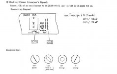
Is the EFM pattern you refer to the "EF Phase Lissajous's figure shown in the attached (from the cdk-006 manual)? The circuitry differs in the 605ES so I will have to try and figure out the test points if that is correct.
Thanks!
Is the EFM pattern you refer to the "EF Phase Lissajous's figure shown in the attached (from the cdk-006 manual)? The circuitry differs in the 605ES so I will have to try and figure out the test points if that is correct.
Thanks!
Attachments
Hi pedrickj,
1.25 Vp-p sounds like the RF level is fine on the face of it. Most CD players operate around the 1.2 Vp-p level for Sony heads. Of course some manufacturers differ but the majority are in this range. That and the stopped pattern is clean enough by the looks of things.
The servo adapter varies by manufacturer and even model. I have several of these test adapters, some are simply filters. What I noticed is that the gain settings vary with the CD, and also the filters are not required unless you have to prove the setup to factory procedure. The other thing that was clear was that the adjustment procedures tend to set the gain at that point where both LF and HF noise is at a minimum. The gain setting method I gave you is valid and avoids wasted time and equipment to arrive at a more than acceptable setting.
E-F balance is basically setting the E and F diodes in the pick-up matrix so that they guide the main beam on the centre of the track. When the track is interrupted, the beam should naturally pick it up again on target. The E and F beams ride on either side of the track with the A,B, C and D diodes falling in the centre. The E and F diodes are used to detect the track edges, and their error signal goes to the tracking servo. The main beam hits the A through D diodes and that is used for focus and actual data, in the form of an RF signal. It isn't digital yet.
I have never, ever heard of a Lissajous figure (display) being used to balance the E and F diode outputs. Normally they simply kill the tracking servo gain and centre the resulting hunt waveform. My method agrees with the normal procedure, and it is more precise plus easier to perform. Faster too. Something else to consider, it wouldn't be the first time an alignment procedure in a manual is completely wrong! Your common sense here will save your skin.
-Chris
Hi. I'm thinking the fault can be caused by other problem. I'm thinking that the laser pickup can't move along the rail, there is anything that block or impede the laser pickup movement, check that the laser pickup can move along the rail, particulary to the center of the disc, in the TOC zone. Maybe is anything that impede the location of the laser pickup in the TOC zone. Best regards
Hi ManoloMos,
That is a good thought. I assumed this was checked.
That eye pattern is of the data area and not the TOC for example.
That is a good thought. I assumed this was checked.
That eye pattern is of the data area and not the TOC for example.
Yeah - nothing impeding the laser movement. I also downloaded an onkyo dx-g10 service manual as it uses the BU-1E optical block as well. A lot of the front end circuitry was the same and there was some additional trouble shooting info in it but it didn't help me much. I put the covers back on and will take it to a local shop for diagnostics - I had high hopes I could do it myself but not this time.
Probably will take it to a shop called Inner Sound near Portland Or. as they seem to have good reviews. Hopefully they will just need to make adjustments.
Thanks for the help!
Probably will take it to a shop called Inner Sound near Portland Or. as they seem to have good reviews. Hopefully they will just need to make adjustments.
Thanks for the help!
Hi pedrickj,
I wish it was here in front of me. So much information is available when thhe machine is in front of you that never gets across a forum or email.
If you wind the head out intothe data part of the CD, a bit out away from the centre position, teh first thing the controller should do is pull the head back towards the spindle / disc motor. Normally slightly out again as well. There is a switch it hits to tell the processor where the head is before it reads data. Does it do that?
-Chris
Chris, and all the others that have tried to help above,
Are you still monitoring this forum? It's been a while since I posted. I took my player to Inner sound in Portland and they said it was the laser. They said parts were not available and took my $100. I now know it is NOT the laser as the laser assembly works fine in a different model but compatible CD player.
I really don't want to give up on this unit. Is there any way to contact any member of this forum (or fellow hobbyist) that is a potentially retired (or not) technician/enthusiast that lives within a few hours driving distance from Portland, Oregon that works on vintage CD players?
I guess I will start looking into potential motor and sled troubleshooting as that was suggested, but if I could find someone semi local to connect with, that would be great.
Thanks,
Jeff
Last edited:
Ok, did a little more troubleshooting. Moved the slide fully to the outer position, put in a disk and the slide moved all the way to the minimum radius so it looks like the slide travel is ok. (Also, in the temporary transplant to the other player, the optical block and the slide/rails/sense coil all went together and were confirmed working). Next I pulled the spindle motor circuit board. There is essentially zero side to side end play of the stator. Axial play of the stator (with out the circuit board restraining it) is probably a mm. Each on of the 4 motor windings measure 13 ohms so no short/opens in the motor. The stator spins freely (with the cb removed). I read somewhere else that axial oscillation of the stator and drive axle can impact disc reading and that you can tape a penny to the top of the cd (which i guess means to the top of the clamp) to add some weight and reduce vibration, but I have not tried that yet. Seems like there should be a way to verify spindle rpm by looking at the out of either of the two hall effect sensors but have not tried that yet.
Thanks for continued help if this thread is still be looked at (player was in the shop for 3 months and then went back in the closet til I decided to not give up)
Thanks for continued help if this thread is still be looked at (player was in the shop for 3 months and then went back in the closet til I decided to not give up)
If you are sure that the laser unit is good, the problem could be caused by different causes. First of all, you could starting to check all voltages from voltage regulators, 5, +15, 15V, etc
When you turn on the cd player, the lens do the up and down movement? This is fundamental too.
When you turn on the cd player, the lens do the up and down movement? This is fundamental too.
Yes, lens goes up and down. I will check all voltages. The optical head, associated ribbon cable, rail/slides, linear motor and sensor are easily moved between players and are all the same part numbers. The RF board differs between the BU-1E and BU-1C optical blocks so that drives the boundary of the transplant. The BU-1C parts are verified working. As far as voltages go, I have not replaced nor tested all the electrolytic caps yet but none are bulging and are all original 1987 ish.
Hi pedrickj,
I'm really sorry to hear of your troubles. Not fun. Paying $100 for nothing isn't great either, that shop should have not charged you anything.
It's been a while. Look for the EF or eye pattern test point, monitor with a scope. 0.5uS/div horizontal and usually 0.5 V/div vertical are the settings.
The CD spins at very approximately 500 RPM in the centre. It locks to the VCO inthe CD player and referenced to the oscillator, correction applied to the motor to lock it to the correct speed. If the E-F balance is of a little, it can't lock (don't touch it!). Focus and tracking adjustments are more forgiving. However don't touch any adjustments before confirming you haven't got any other failures. Adjustments should be good, touch them LAST.
Too bad the other shop was in there. Now you don't know if anyone twisted control positions. That's what I hate about getting equipment in someone else has attempted to repair. You waste a lot more time. Everyone always twists pots first. "Maybe it's just an adjustment". NO!
Ready to give up again. I replaced all electrolytic caps - I was just going to remove them one by one and test them but then decided I might as well replace them if I was going through all that work. I did find a couple that were out of spec so it was worth a shot. Didn't help.
Downloaded a couple pdfs on CD player servicing and have been working through them, taking notes, correlating them to the schematics in the service manual.
Worked through the adjustments with the following results.
The Focus OK signal shows good so I don't think there is anything out of whack with the focus servo (Error or Gain)
Laser power is set to the current noted on the optical block so that should be good and assume the FOK also confirms that.
Set the VCO into tolerance, but toward the upper end as that is what one of the books said to do.
Spindle servo loop seems ok as as the clock switches to the crystal frequency.
Eye pattern looks pretty crisp and the EFM squared off signal is there.
It still does do nothing more than spin the disk up ( and stays spinning) but does not read the TOC.
I played with the Tracking Balance and the Tracking Gain to optimize the eye pattern which still looks good.
Kind of don't no where to go from here - I guess it could be something in the decoder chip or RAM or some aspect of the digital data handling.
I wish there was some way to find a fellow hobbyist expert in the vicinity of Portland Oregon who would want to play with this and let me look over his/her shoulder to confirm this is a lost cause. I guess its going back in its box in the cupboard, maybe forever this time.
Thanks for all the help! (I did learn a lot)
Hi pedrickj,
Sorry you aren't close.
So you have a good eye pattern, stable. That means all servos are locked. Good. The EFM signal should go into the DSP where information is then sent to the CPU, and the DAC section (probably digital filter next). Look for activity from the DSP into the CPU, you may find an open connection or shorted signal. You know the CPU should be working on some level as it executes commands from the keyboard. If there is a servo controller, make sure it is running, it would (if exists) go between the DSP and CPU.
Some logic is working, that much is certain. Your problem isn't common at all.
- Home
- Source & Line
- Digital Source
- CDP-605ES Error amp bias adjustment