I'm modding a Philips CD304 MKII and am looking at the output stage.
Having seen many TDA1541 based player schema's I haven't seen this before (see picture). There is even a special regulator on the decoder board for this. To me being in the signal path it looks like a bad thing.
Can someone explain/advise?
Wouter
Having seen many TDA1541 based player schema's I haven't seen this before (see picture). There is even a special regulator on the decoder board for this. To me being in the signal path it looks like a bad thing.
Can someone explain/advise?
Wouter
Attachments
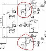
Perhaps it is an attempt to reduce offset errors in the NE5532 and following circuitry by injecting a current into the virtual ground point.
How does that resistor and cap (the 2K7 and the 10uf cap) affect the "noise gain" of the opamp by it "throwing away" some open loop gain ? Sonically that can be beneficial in the right circumstances but I'm not sure how it works out in this configuration as an I'V convertor.
How does that resistor and cap (the 2K7 and the 10uf cap) affect the "noise gain" of the opamp by it "throwing away" some open loop gain ? Sonically that can be beneficial in the right circumstances but I'm not sure how it works out in this configuration as an I'V convertor.
Can someone explain/advise?
TDA1541 has -2mA current offset on L/R outputs...Those resistors and cap are for nulling that current offset (8VDC/4k9=1,63mA) so output could be DC coupled (with dc servo)
- Status
- This old topic is closed. If you want to reopen this topic, contact a moderator using the "Report Post" button.