CD104 reads CDRs but not CDs [solved]
Hello,
Well the title says it all.
To see what was done and thought so far, please start from here:
http://www.diyaudio.com/forums/digital-source/32591-philips-cd104-tweaks-78.html#post3488293
Thanks for your ideas!
Hello,
Well the title says it all.
To see what was done and thought so far, please start from here:
http://www.diyaudio.com/forums/digital-source/32591-philips-cd104-tweaks-78.html#post3488293
Thanks for your ideas!
Last edited:
Hi!
A though one eh.
Perhaps somebody has the phone number of the Dutch engineer who designed the machine (-;
A though one eh.
Perhaps somebody has the phone number of the Dutch engineer who designed the machine (-;
I've just measured my own CD104b whilst playing:
CD/CDR eye pattern = 1Vpp/0.7Vpp, pin1 ic6212 = -4V/-5.5V
Yours is ?/1Vpp, 0.25?/-7
Are you sure your CDR eye pattern is 1Vpp, not 0.5Vpp
I note adjustments section of the manual gives pin1 as -4 +/- 2V
CD/CDR eye pattern = 1Vpp/0.7Vpp, pin1 ic6212 = -4V/-5.5V
Yours is ?/1Vpp, 0.25?/-7
Are you sure your CDR eye pattern is 1Vpp, not 0.5Vpp
I note adjustments section of the manual gives pin1 as -4 +/- 2V
Yes I'm sure.
Now I can't play CDRs! Yesterday I could (even from cold) and today...
What has changed? The radial motor never moves again, it just sticks to the motor spindle as soon as I power up.
In loop A I still measure the same voltages though.
I've ordered a TCA240, we'll see.
Now I can't play CDRs! Yesterday I could (even from cold) and today...
What has changed? The radial motor never moves again, it just sticks to the motor spindle as soon as I power up.
In loop A I still measure the same voltages though.
I've ordered a TCA240, we'll see.
Right then.
I have re-checked, I've got no AC signal at pins 12 and 13 of TCA240 (service loop A), so nothing either (just noise) at pin 8 of 6215 op-amp.
The real question is: what has it worked with CDRs until yesterday? Is it possible that one branch of the TCA still worked and that it finally gave up the ghost?
More of which when it is replaced, I can't wait.
I admire your determination with this although I still feel the problem will come down to to the RAFOC.
What do Philips call the "focus OK" signal. Have you checked to see if there is any change on that line as the RAFOC does a focus search (with a disc present of course)
What do Philips call the "focus OK" signal. Have you checked to see if there is any change on that line as the RAFOC does a focus search (with a disc present of course)
I think that the tracking loop doesn't work because the transistors in the TCA are open circuit.
Radial error 1 and 2 signals (the difference is the final tracking error signal) can't find their way to the radial motor.
The error signals from the photodiodes are present and conform.
Radial error 1 and 2 signals (the difference is the final tracking error signal) can't find their way to the radial motor.
The error signals from the photodiodes are present and conform.
Have you scoped and measured voltages on the TCA. Any problems related to one of the six transistors should show in measurement.
Yes I have. Everything comes in nicely but nothing gets out!
Test points 24 and 25 show correct values, but nothing gets out at points 27 and 28, both signals going to the LM324 integrator.
Test points 24 and 25 show correct values, but nothing gets out at points 27 and 28, both signals going to the LM324 integrator.
An externally hosted image should be here but it was not working when we last tested it.
Last edited:
That doesn't necessarily mean its faulty unfortunately. All the evidence is in the voltage and/or dynamic signals present (as viewed on a scope) on those transistors and whatever is present, (whether right or wrong) should enable a good judgement of whether the transistors are functioning correctly.
Yes, I meant AC signals, not DC! Test points 22 and 23 also show correct peak to peak values of course.
Or am I being stupid?
Or am I being stupid?
It hard to say without actually probing it and getting a feel for what is going on. Is there a zener just out of sight above the IC, a 2.4 volt one. Has that got 2.4 volts across it ?
Is it marked as a 2V4 zener on your circuit ? If it is then check from ground to the zener to make sure the supply is correct.
I'm not actually working from CD104 circuit but a CD303 which seems similar.
I'm not actually working from CD104 circuit but a CD303 which seems similar.
I'm using the Beogram CDX schematics, which are actually more precise!
The above diagram comes from the CD104 manual.
The above diagram comes from the CD104 manual.
I'm using the Beogram CDX schematics, which are actually more precise!
The above diagram comes from the CD104 manual.
This is the 303
Attachments
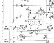
The voltages are slightly different here than on both Philips and B&O manuals.
But the components are the same !
But the components are the same !
Its worth looking at and around the zener although low voltage zeners can be very misleading appearing faulty when they are not.
That said, if its passing current then it should definitely develop around 2.4 volts across it, but it will only pass significant current when the TCA is conducting and there is a path to ground. If in doubt connect something like a 10K from ground to the diode to pull a little current and check the voltage again.
That said, if its passing current then it should definitely develop around 2.4 volts across it, but it will only pass significant current when the TCA is conducting and there is a path to ground. If in doubt connect something like a 10K from ground to the diode to pull a little current and check the voltage again.
OK, probably no real surprise there.
So your back to the TCA. Guess you have to just wait for the new IC now (or try one from another player).
At the back of my mind I still think its RAFOC related because the electronics have "proved" workable by playing CDR.
But keep trying and thinking on the problem 🙂
So your back to the TCA. Guess you have to just wait for the new IC now (or try one from another player).
At the back of my mind I still think its RAFOC related because the electronics have "proved" workable by playing CDR.
But keep trying and thinking on the problem 🙂
- Status
- Not open for further replies.
- Home
- Source & Line
- Digital Source
- CD104 reads CDRs but not CDs