Is this a continuation of this thread you started ? - Vintage CD Player woes .. need to pick the brains of the techies in the house.
many high end manufacturers recommend replacing caps every 13- 15 (AS REGULAR MAINTENANCE) years in their kit for a reason,
Seriously? You just made this up right?
This is incorrect, but if it were true, it would be a clear case of snake-oil.
Jan
Seriously? You just made this up right?
This is incorrect, but if it were true, it would be a clear case of snake-oil.
Jan
Then you are just as bad as that other guy. And no, I didn't make it up, Have a look at Naim Audio's service schedule as an example. I have replaced aging caps in machines that worked perfectly fine and noticed several differences. The caps were measuring way off their values due to age, but the machine was still working fine, however, sound quality will degrade over time, as will other levels of performance. But .. I am probably wasting my time talking to someone like you, so this will be all I say to you on the matter.
Seriously? You just made this up right?
This is incorrect, but if it were true, it would be a clear case of snake-oil.
Jan
Once they start to bulge, it is best not to wait until they spew their guts out all over the PCB.
Let's take the typical CD player having a current-output DAC, and let's take the typical I/V converter consisting of an operational amplifier and a single feedback resistor. The conversion ratio is determined by the feedback resistor (typically 1.5k or so). Now if the resistor is broken and goes out of spec, the gain might go up. But this unlikely to happen in both channels at the same time.
(There might be some unprofessional tampering and cold solder joints - GotHifi don't take it on yourself, are you the first owner of this player?)
(There might be some unprofessional tampering and cold solder joints - GotHifi don't take it on yourself, are you the first owner of this player?)
Let's take the typical CD player having a current-output DAC, and let's take the typical I/V converter consisting of an operational amplifier and a single feedback resistor. The conversion ratio is determined by the feedback resistor (typically 1.5k or so). Now if the resistor is broken and goes out of spec, the gain might go up. But this unlikely to happen in both channels at the same time.
(There might be some unprofessional tampering and cold solder joints - GotHifi don't take it on yourself, are you the first owner of this player?)
I am not, and I know someone has been inside it before, but in looking at it closely, everything does look original.
Have a look at Naim Audio's service schedule as an example.
Where is that?
Jan
How come we have gone from discussing a "high output" on a B&O CDX player to talking about the digital output from a shigaclone?
Mods please split.......
.
Mods please split.......
.

Posts on DAC level when used with different source components are now here:
Question on DAC output levels when used with different source
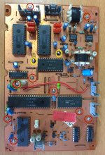
So just an update, I think it is pretty safe to say that this issue is narrowed down to the decoder PCB. (board with DACS, OS chip, etc) ...
I have now swapped out the CD Mech, Power supply board, and Servo board from spare parts I have. The problem still persists.
I haven't swapped out the decoder board as the spare I have has other issues. However, not the same issues as this one, so surely there is a part on it somewhere I can use to fix this issue. The hunt is on! 😀
op amps have been replaced and all questionable solder joints have been redone. So, that leaves resistors. There are 2 surface mount resistors on the bottom of each op amp, but I couldn't get them off.
CDX service manuals are freely available, e.g.
Browse Beogram - Beogram CDX manuals
BANG OLUFSEN BEOGRAM CDX Service Manual download, schematics, eeprom, repair info for electronics experts
The CDX is dual TDA1540 DAC with separate NE5532 output stages for left and right, so a problem on both channels is very unusual.
The service manuals have the schematics, layouts, component numbers & values, and list the expected voltages and waveforms. First step would be to compare expected voltages on the decoder board while the error is happening.
The CDX is dual TDA1540 DAC with separate NE5532 output stages for left and right, so a problem on both channels is very unusual.
This is odd, and "should" make things easier as it pretty much rules out anything to do with dacs/op amps, or resistors per channel.
Griplets, I was trying to remember the name after I realised it was TDA1540 and immediately remembered the Philips CD104, then thought nahhh, obviously they've all been checked 🙂
Out of interest, do you know where this was in the circuit?
Out of interest, do you know where this was in the circuit?
Griplets, I was trying to remember the name after I realised it was TDA1540 and immediately remembered the Philips CD104, then thought nahhh, obviously they've all been checked 🙂
Out of interest, do you know where this was in the circuit?
lol yeah, and they were the first thing I did, doesn't help much when you miss one!

It was the one in the green and red circle above and the right of SAA7020
Attachments
- Home
- Source & Line
- Digital Source
- CD player output extremely high