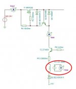
I'm working on a new project where I'll possibly need to deploy a CCVS (Current controlled voltage source). It is transconductance amplifier or converter and many manufacturers offers transconductance amplifier but in form of a VCCS (Voltage controlled current source). In practice I need CCVS with 0.5ohm (or 500mV/A). When using simulation like one in TINA (please see attached image) it's easy: there you can choose ideal CCVS and everything works perfect: for let say 5mA of current it's "mirroring" 2.5mV. I was playing with different current mirror topologies (with 2 to 4 transistors) and the best what I got is predictable "transfer" of 100 ohm, that means for 1mA of the current (Ibias on the picture) 100mV (Vbias). Something that seems to make things more challenging is that emitter is connected to approx. -6V (-15V + 9.1V zener) but this is another story. First I need to get a precise 0.5ohm "mirroring". Many thanks in advance for any suggestion how to proceed.
Attachments
You want a transimpedance amplifier - the opposite of a transconductance amplifier. There are many ways you could accomplish this, depending on what you want the voltage for (does it need to be ground referenced? How accurate does it need to be?)
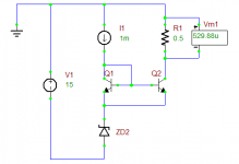
If you want to use a current mirror, the attached schematic shows what immediately springs to mind. It's only approximately 0.5Ω, it's inverting, and it doubles the current through the Zener, but it's simple. You could put it on the other side of the Zener to fix that last issue, but I presume you wanted it in the same place as the CCVS in your schematic.
Another possibility would be to use an op-amp connected as a differential amplifier with the inputs across R13.
Attachments
- Status
- Not open for further replies.