Dear audio enthusiasts,
I read a lot here and enjoy the brilliant expertise shared by the forum members.
Recently, I came across an interesting thread discussing one of the countless variants of what I just called the Hitachi style push-pull VAS in lack of a better term.
Keantoken presented his design and BesPav suggested a few improvements: Keantoken's Aurum-X 300w Amp with LatFETs
I don't want to hijack the other thread as the decision was to basically stick with the original design and not to implement most of the suggestions.
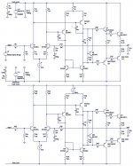
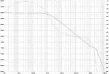
Using a minimized model amplifier, I simulated the suggestion to replace the tail resistor of the VAS LTP by a current source and while this is an interesting idea, I can't see the big improvement, but new problems coming with the CCS.
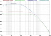
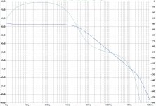
Below you can find screenshots and also the LTSpice file.
Did anybody succeed with using a CCS for the VAS LTP?
What would be the possible improvement?
Best regards,
Lee
I read a lot here and enjoy the brilliant expertise shared by the forum members.
Recently, I came across an interesting thread discussing one of the countless variants of what I just called the Hitachi style push-pull VAS in lack of a better term.
Keantoken presented his design and BesPav suggested a few improvements: Keantoken's Aurum-X 300w Amp with LatFETs
I don't want to hijack the other thread as the decision was to basically stick with the original design and not to implement most of the suggestions.
Using a minimized model amplifier, I simulated the suggestion to replace the tail resistor of the VAS LTP by a current source and while this is an interesting idea, I can't see the big improvement, but new problems coming with the CCS.
Below you can find screenshots and also the LTSpice file.
Did anybody succeed with using a CCS for the VAS LTP?
What would be the possible improvement?
Best regards,
Lee
Attachments
-
 IPS_VAS-CCS_schematic.JPG91.9 KB · Views: 523
 -
 IPS_VAS-CCS_AC.JPG243.9 KB · Views: 478
 -
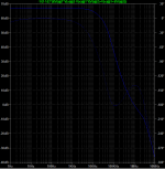
 IPS_VAS-CCS_PSRR.JPG206.6 KB · Views: 383
 -
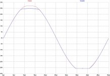 IPS_VAS-CCS_clipping.JPG119.5 KB · Views: 361
 -
 IPS_VAS-CCS_loopgain_normal.JPG247.7 KB · Views: 353
 -
 IPS_VAS-CCS_loopgain_CCS.JPG247.7 KB · Views: 210
 -
IPS_VAS-CCS.asc15.3 KB · Views: 91
Last edited:
Check "folded cascode", it's a well known arrangement of pair of common emitter and common base stages.I came across an interesting thread discussing one of the countless variants of what I just called the Hitachi style push-pull VAS in lack of a better term.
Using a minimized model amplifier, I simulated the suggestion to replace the tail resistor of the VAS LTP by a current source and while this is an interesting idea, I can't see the big improvement, but new problems coming with the CCS.
Now you check loopgain, but try to check +V rail PSRR.
😉
Did anybody succeed with using a CCS for the VAS LTP?
What would be the possible improvement?
AD797 did. Just think what the R3 and R4 on the crystal is and check this in the figure 33 of the datasheet.
😉
Now tuneup frequency correction and you're pick additional +10 dB loopgain with proper PSRR.
If R3, R4 are active loads such as current mirror, the VAS must has a CCS to determine its Iq.
It does.
But not a mirror, just different CCS for different shoulders.

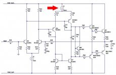
I think you are asking about the constant current source marked in red below ?
If so, it operates with very little voltage between the (+) terminal of the CCS and the (-) terminal. I don't think you'll have sufficient voltage headroom to use a cascode circuit there. I myself would probably choose a PNP-BJT current mirror, for high output conductance with very low voltage drop. Slightly more complicated but much better performance.
Since there can't be very much voltage dropped across emitter degeneration resistors, I believe I would tend to select a PNP whose Early Voltage was exceptionally high. Something like the ZTX757 below.
_
Attachments
I think you are asking about the constant current source marked in red below ?
Oh, Mark, you open my eyes!
This is not a CE-CB folded cascode.
This is simple double LTP's, but first are resistor-loaded, while second one are current-mirror loaded.
The current source makes the common-mode impedance very high, rather than very low, which has a big effect as the LTP in the VAS isn't vaguely symmetrical, one side is swinging full rail, and pumping current back through the Miller compensation cap, the other isn't swinging at all.
I think the big change is that Q15's emitter is floating at a fairly high impedance, compared to Q4 emitter bound to the rail by 50 ohms - thus the current fed back from the Miller cap is generating much more voltage than it should (rather than current-summing into the IPS)
Does removing C7 and C11 make any difference at all BTW? I think they aren't doing anything.
What would be the possible improvement?
I'ld try something like attached if keep noninverting and EF2 at the output.
Attachments

Disconnect R25-R26 from the top rail, and install two diodes connected in series, between R25-R26 and the Vrail.
Thanks for your great ideas so far!
I tried to simplify the schematic in order to isolate the problem. However, this didn't go so well since I simplified too much. Removing the cascodes from the VAS LTP makes too much difference.
Thanks for pointing out how the dual LTP front end can be made to use a current mirror in the first LTP. Not having a current mirror in the LTP risks the balance of the LTP, doesn't it?
What I'm actually working at, is a front end heavily based on Bob Cordell's amplifier presented here: http://www.cordellaudio.com/papers/MOSFET_Power_Amp.pdf
His amp features a clever active load with common mode current control circuit for the input LTP, which Bob also explained here: Unipolar vs complementary input stage
As I still struggle to fully understand Bob's four transistor common mode current control loop and buffer stage, I wonder whether it also acts like a current mirror somehow as well. Could this arrangement profit from an additional current mirror in the first LTP, which would then in turn require a current source in the VAS LTP?
I simulated adding a current mirror to the first LTP plus CCS to the second LTP and it seems to work, but I'm not sure whether it is a good idea. Attached is the idea sketched. What do you think?
Best regards,
Lee
Attachments
- Home
- Amplifiers
- Solid State
- CCS used in Hitachi style push-pull VAS LTP