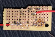
I'm struggling with the CCS's I'm trying to put on my 12B4 plates. I've got a cascaded DN2540 and DN3545 with 510r gate stoppers. The bias is a resistor and pot in parallel for adjustability. I've gone over it a bunch of times, and I'm sure it is wired correctly. I wired one into an amp, with the 12B4 pulled and a 100r resistor from the tube pin to ground. I then started bringing to voltage up with a variac (SS rectified, so I can have the voltage quite low). It seems that output current (measuring voltage across the resistor) varies with the input voltage, and it gets far too high. Also, pardon my not knowing how this stuff works, but shouldn't I measure a high resistance across the CCS? From input to output, all I measure is the bias resistance, so it seems like the Fets are shorts. It seems to me like it isn't working. I attached a pic of the CCS that isn't installed.
What am I doing/have I done wrong?
Paul
What am I doing/have I done wrong?
Paul
Attachments

Could you post a schematic? I could probably trace it from your photo if I had an hour. 😀
edit: why is the pot in parallel rather than series? You're going to want something like 1.7-1.9V of bias, which means that for a 20mA current (just guessing), the source R will be ~80-120R. If the pot is turned down in a parallel circuit, the CCS will run away.
edit: why is the pot in parallel rather than series? You're going to want something like 1.7-1.9V of bias, which means that for a 20mA current (just guessing), the source R will be ~80-120R. If the pot is turned down in a parallel circuit, the CCS will run away.
Here's the schematic from which I borrowed it. I believe it (the resistor values) is/are Bandersnatch's work, drawn by somebody over at another forum. The CCS is essentially what I've seen you draw, but with a cheaper fet in the second position and the pot for adjustability.
Paul
Paul
Attachments
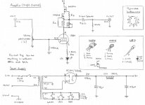
Lose the pot and see what happens. The current should be low (10mA or so); if it's not, you may have fried a FET. Also, the output cap should be coming off the tube plate, not off the FET source. And bleeder resistors on the power supply are a good idea if you don't want to accidentally fry yourself.
What is that output coming from top of set resistor? I have seen anti triode coming from a two resistor midpoint, but this one? An error, or some lower impedance point?
Wouldn't that be the so-called mu-output, providing a lower source impedance as seen by the next stage?
What is that output coming from top of set resistor? I have seen anti triode coming from a two resistor midpoint, but this one? An error, or some lower impedance point?
The output at the top of Rset, is a low impedance (but somewhat higher distortion) output. As SY said, if the pot in parallel with Rset is set to low resistance, current will run away.
One possible problem: I once downloaded a Supertex data sheet (from their site) that had incorrect lead assignments for the TO92 part. Found out after I fried a couple, and then found a newer data sheet. Looking at the flat side of the TO92, leads are (L to R), SGD - Not the same as the TO220 part, which is GDS.
Sheldon
Edit: on second look, your schematic appears to have the correct lead assignments.
Last edited:
Try it with 2 x DN2540, no pot and a low value Rset (I think I remember about 200R giving in the region of 10mA).
If you are going to substitute the tube for testing then consider replacing it with a resistance of equal value (not your 100 Ohms).
Make sure the power supply is working 100% as expected before conecting anything to it.
( LED and a large value resistor seems odd in the cathode ).
Higher distortion? Are you sure? I thought the 'mu' output would let the output track across the anode curves without current fluctuation, and hence reduce distortion by a country mile? At the same time the upper FET should shield against power supply fluctuation to some degree.
Assuming low circuit loading (i.e. highish Z from the subsequent circuit) then only a tiny AC / music signal current will be drawn from the power supply.
(If I am wrong please spell it out so that I can learn. Thanks).
If you are going to substitute the tube for testing then consider replacing it with a resistance of equal value (not your 100 Ohms).
Make sure the power supply is working 100% as expected before conecting anything to it.
( LED and a large value resistor seems odd in the cathode ).
The output at the top of Rset, is a low impedance (but somewhat higher distortion) output.
Sheldon
Higher distortion? Are you sure? I thought the 'mu' output would let the output track across the anode curves without current fluctuation, and hence reduce distortion by a country mile? At the same time the upper FET should shield against power supply fluctuation to some degree.
Assuming low circuit loading (i.e. highish Z from the subsequent circuit) then only a tiny AC / music signal current will be drawn from the power supply.
(If I am wrong please spell it out so that I can learn. Thanks).
I think I've got it working. I'm not sure what my problem was. I moved the output connection to the bottom of the resistors. Though I'll watch to see if you guys decide it was originally as drawn for a reason rather than a mistake. FWIW, I'm not using that power supply, just the CCS. The guy who drew the schematic put the LED there as an indicator, not to play a role in biasing. Now if only the switch to CCS loading and adding another LC stage to the PS had solved my problem . . . But that is a story for the original thread.
Paul
Wild Burro Audio Labs - DIY Full Range Speakers
Paul
Wild Burro Audio Labs - DIY Full Range Speakers
If the pot was set to near-zeros ohms when it was first turned on, the FETs are prolly toast. The circuit was originally drawn like that because I made PCBs, and the two resistors were never originally made to be both in place. Once the proper resistance was determined, the pot would be removed and the resistor of proper value would be put in place.
With no power applied, you should be able to measure across the pot and resistor and adjust to the approximately-needed-value by trimming the pot, then apply power and tweak until your desired current is met. This is actually how I've been running them, and they work fine, as long as you are careful on the first turn-on.
What is not shown on that schematic is some gate protection zeners -> two 18V zeners cathode-to-cathode from each FET gate stopper to source.
The LED and resistor was in there, simply as an indicator that the circuit was working (can put it on the top-panel or something).
I am also under the impression that the bottom-FET source will exactly track the plate, and hence have the same distortion. If the plate current is constant, then the set resistor current must be constant, and hence the voltage drop across it is constant. Hence, the mu-output is just a few constant volts above the plate, so distortion should be the same.
Higher distortion? Are you sure?
No, not sure. I have it referred to on a schematic that way, but I can't find the original source. I very well may have gotten it wrong, because I have no mechanistic argument for it. As you say, distortion with a heavy load would favor the mu connection.
Sheldon
I enjoyed reading this article on active loads. Has some info on mu output. Maybe it will be useful.
Active loads and signal current control
Active loads and signal current control

Weird behavior in CCS circuits is sometimes caused by high frequency oscillation in the megahertz range. This can also cause the CCS to appear to be working normally but not sound as good as it could.
Since there is always some load, even a grid resistor, the mu output (top of Rsense) should always give a flatter load line than the CCS output (bottom of Rsense) and thus lower distortion. People have, though, reported liking the sound of the CCS output better... Some have reported liking a resistor better than a CCS. People have also reported liking e.g. a 5842 at 10mA vs. 20 mA... I guess some people like distortion ;-) ;-) We *are* talking mostly a difference in 2nd harmonic.
The mu output is super low impedance, in the 10-50 ohm range, and will easily drive grid current if the coupling allows, while keeping the driver tube on a flat load line.
I wouldn't think the DN3545 would be my first choice for a bottom device; it has somewhat high capacitance at low Vds, and at tube circuit currents increasing temperature will cause increased current. Why not a TO-92 DN2540 here?
Likewise, using a 10M45 or IXTP01N100 as the top device would give you almost one more volt of Vds for the bottom device. Not sure if any of this would impact the sound but might perform a little better electrically.
Cheap MOSFET ~= $0.80, pricey MOSFET ~= $1.40 ...
In this circuit the gate protection zeners might not be absolutely needed, but certainly won't hurt.
5K-10K would be a more representative test load; with a small resistor you will need to drop all the voltage across the CCS and it may get hot.
Second the recommendation to read Gary Pimm on CCS, also Walt Jung in AudioXpress
http://www.audioxpress.com/magsdirx/ax/addenda/media/jung2779.pdf
Cheers,
Michael
Last edited:
In this circuit the gate protection zeners might not be absolutely needed, but certainly won't hurt.
But with depletion mode MOSFETS you do need to use 2 zeners in series back-to-back to allow for negative gate voltage. Otherwise it will force high current through the MOSFET.
Also: It might be OK to use a single zener but wired as with a p-type enhancement device, i.e. with depletion devices you could wire the anode of the zener to the gate of the MOSFET.
Michael
Last edited:
- Status
- Not open for further replies.
- Home
- Amplifiers
- Tubes / Valves
- CCS Troubles