Ok, sorry, I try again !. This time I'm trying to send a jpg image file.
Hello All,
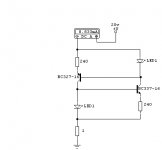
This 2 terminal constant current source circuit is shown in a recent EW magazine - Circuit Ideas.

The formula given is - Iconst = 2 * [(Vf - Vbe)/ R], where
Vf = Led voltage drop,
Vbe = vbe for Tr1 & Tr2,
R = R1 = R2.
Simulation with red leds shows
10v - 8.810 mA
20v - 8.833 mA
30v - 8.854 mA
40v - 8.873 mA
50v - 8.891 ma
Maybe this is old hat to some of us, maybe useful to others of us.
Modifications/improvements ?.
Is this good performance ?.
Is there more to be known regarding application of ccs's.
HH thoughts on green leds ?. 🙂
Regards, Eric.
Hello All,
This 2 terminal constant current source circuit is shown in a recent EW magazine - Circuit Ideas.
"Constant current diode look-alike" ....... .........The 2 terminal circuit shown here is composed of a pair of complimentary constant current sources, where each provides a constant current for the voltage reference of the other, thereby improving performance.
Compliance is excellent and the current can be set to almost any value.
Power dissipation and voltage withstand are limited only by the transistors chosen.
The circuit can be made up on a tiny piece of stripboard, and makes an excellent replacement for current setting resistors in many audio power amplifiers.
David N J White
Bearsden
Glasgow
G3
The formula given is - Iconst = 2 * [(Vf - Vbe)/ R], where
Vf = Led voltage drop,
Vbe = vbe for Tr1 & Tr2,
R = R1 = R2.
Simulation with red leds shows
10v - 8.810 mA
20v - 8.833 mA
30v - 8.854 mA
40v - 8.873 mA
50v - 8.891 ma
Maybe this is old hat to some of us, maybe useful to others of us.
Modifications/improvements ?.
Is this good performance ?.
Is there more to be known regarding application of ccs's.
HH thoughts on green leds ?. 🙂
Regards, Eric.
mrfeedback, please use the "attach file" box on your .jpg image. This will upload it to the diyaudio server. It is smart enough to know that a .jpg is an image it can display. If you send a .bmp this way it will be attached, but not displayed.

I can see it! I actually deleted an attempt to put my guess of a picture in for discussion since you were not yet successful.
mlloyd1
mlloyd1
Ahhh, success at last. Thanks for the replies telling me so !.
Can you read the previous text too ?.
Comments etc ?.
Regards, Eric.
Can you read the previous text too ?.
Comments etc ?.
Regards, Eric.
If you want an even more extreme current source use cascodes and if you want even more use darlington connection for the "upper" transistors.
Instead of LED (temperature sensitive and not very predictable) use a LM431! Now the current source starts to look my kind of style (overkill and monster design)!
Instead of LED (temperature sensitive and not very predictable) use a LM431! Now the current source starts to look my kind of style (overkill and monster design)!
Eric
Thanks for posting the schematic (eventually 🙂. Apart from the advantage of it being a two terminal arrangement, I don't see too much benefit in the circuit. In simulation, the current variations with ambient temperature and load are slightly greater than those for a standard LED/transistor ccs. The current change with supply rail voltage variations is however significantly better, but this is only of relevance if unregulated supplies are used.
The standard two-transistor ccs has better temperature characteristics and far better load tolerance than either of the LED circuits and is mid-way between the two LED circuits so far as current v supply rail voltage is concerned.
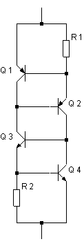
The two-transistor ccs can be made into a two terminal arrangement, as shown below, using a similar philosophy to the circuit you posted. With this ccs, the temperature and load characteristics are similar to those of a standard two-transistor ccs and the current change with supply rail variations betters David White's circuit by a factor of 10.
Geoff
Thanks for posting the schematic (eventually 🙂. Apart from the advantage of it being a two terminal arrangement, I don't see too much benefit in the circuit. In simulation, the current variations with ambient temperature and load are slightly greater than those for a standard LED/transistor ccs. The current change with supply rail voltage variations is however significantly better, but this is only of relevance if unregulated supplies are used.
The standard two-transistor ccs has better temperature characteristics and far better load tolerance than either of the LED circuits and is mid-way between the two LED circuits so far as current v supply rail voltage is concerned.
The two-transistor ccs can be made into a two terminal arrangement, as shown below, using a similar philosophy to the circuit you posted. With this ccs, the temperature and load characteristics are similar to those of a standard two-transistor ccs and the current change with supply rail variations betters David White's circuit by a factor of 10.
Geoff
Attachments
Geoff,
What an excellent idea! I wonder if bonding Q2 and Q3 togther thermally would provide any thermal stability benefits?
Jam
What an excellent idea! I wonder if bonding Q2 and Q3 togther thermally would provide any thermal stability benefits?
Jam
peranders, could you post an ultimate current source?
As you may know these things are becoming quite popular with tube/valve people. I just installed the C4S from the bottlehead site on my tube preamp, but I was wondering if there was a way to improve on the design. Needless to say I am no EE.
Cheers,
Bas
As you may know these things are becoming quite popular with tube/valve people. I just installed the C4S from the bottlehead site on my tube preamp, but I was wondering if there was a way to improve on the design. Needless to say I am no EE.
Cheers,
Bas
Jam
Difficult to answer your question without actually building and testing the circuit. In simulation, I simply raised the global temperature. A 10degC rise in junction temperature gave a 2.5% current variation for this arrangement, compared with 3.5% for the LED schematic. Current variation with load (10ohm to 1kohm) was 0.1%, the same as the two-transistor ccs, compared with approximately 0.75% for the two LED versions. For a 50V supply rail modulated with a 2Vpeak sine wave, the current variation was 0.004% for the circuit I posted, 0.04% for the White circuit, 0.18% for a standard two-transistor ccs and 0.37% for the LED/transistor version.
Geoff
I should have mentioned in my original post that, for the 4-transistor ccs, R1 = R2 = R and Iconst is 2 * Vbe / R. For initial calculations, R = 1.3 / Iconst is sufficiently accurate.
Sonny
BC550 & BC560, with R1 and R2 set at 120ohm. I adjusted all versions of the ccs to give a current of between 10 and 11mA, which was the figure the White circuit gave with the resistor value shown on Eric's schematic.
I must stress that the figures I obtained should be treated as approximate since I made no attempt to optimise each circuit. However, I believe that they are sufficiently accurate to permit an initial comparison to be made. The main disadvantage I see with the 4-transistor or 2-LED/2-transistor ccs is that a higher supply rail voltage may be needed in certain applications due to the larger PD across the ccs.
Geoff
Geoff
I just the other day was drawing up a CCS, and those are exactly the transistors I was planning to use! I'll have to try out your circuit.
I just the other day was drawing up a CCS, and those are exactly the transistors I was planning to use! I'll have to try out your circuit.
Geoff said:Sonny
BC550 & BC560, with R1 and R2 set at 120ohm. I adjusted all versions of the ccs to give a current of between 10 and 11mA, which was the figure the White circuit gave with the resistor value shown on Eric's schematic.
I must stress that the figures I obtained should be treated as approximate since I made no attempt to optimise each circuit. However, I believe that they are sufficiently accurate to permit an initial comparison to be made. The main disadvantage I see with the 4-transistor or 2-LED/2-transistor ccs is that a higher supply rail voltage may be needed in certain applications due to the larger PD across the ccs.
Geoff
I can understand that, but it could be fine for something like currentsource for an input diff-pair or for driving a bunch off currentmirrors with a constant current source. It will not be affected that much by ripple on the supply rails.
I think your sims shows the fine result you can get with a 4-BJT solution compared to a "simple" current source.
Sonny
Harry
Your's is longer than mine :-( Is this a competition to see who can design the most complicated current source?
Tiroth
By all means try the circuit I posted. However, if your supply rails are regulated (which they should be for low current circuits) I do not see that there will be any performance improvement over a simple 2-transistor ccs. An alternative, if the supply rail voltage does fluctuate, is a jfet (with gate and source connected to from a ccs) in place of collector resistor on the control transistor. The 4-transistor circuit only comes into its own if a two-terminal ccs is required to say replace a resistor in an existing circuit where it is difficult to provide the earth connection required by the simple 2-transistor circuit.
Don't take my reference to the BC550/BC560 as a recommendation (though I have no complaints with these transistors). I simply use the models for these devices when I want a small-signal transistor model since I have tested the models and have found that the results have good correspondence with the datasheet information.
Geoff
- Status
- Not open for further replies.
- Home
- Amplifiers
- Solid State
- CCS reposting