I decided to try this out as a driver for my 2A3. My only deviation from Brett's suggestion was to go for the Bottlehead C4S instead of Gary Pimm's BBMCCCS (even though I saw posts by people preferring the latter), only because the C4S seems marginally simpler to understand/analyse/build.
So... a suggested operating point was 150V, 22mA. I might tone that down to 20/18/15mA, depending on how much the CCS can take, and depending on the answers to some questions here. 150V/18mA is the suggested operating point and that gives me a -4V bias, which requires a 222 ohms cathode bias resistor. Voltage at the plate is 154V so far.
* My main question is, what should my B+ be? The 2A3 needs 45V, so that's 199V at a minimum. 250V? 300V?
Once I figure that out, I can do the rest of the calculations needed on the CCS.
* And a dumb question - if I have a CCS, I don't need a plate load resistor, right? I can take the output straight off the plate?
And finally - I've seen a rule of thumb that states that the driver should have 5x the required current delivery capacity. That brings up several questions:
1) How do I calculate the required current delivery capacity? It seems like it should be the required slew rate (which is voltage/time) times the Miller capacitance at the input of the 2A3. Is that correct? I can figure out how to calculate that Miller capacitance, but what's the required slew rate? 45V/20KHz? Double that for a margin/pad? Something else entirely?
2) After I calculate how much current I need, how do I calculate how much current the driver stage can deliver? The DC bias current flows through the CCS, so does all the signal current go to the load? That doesn't make sense, it's a voltage that drives the 2A3's grid and not a current, right? In a regular plate load situation, the varying signal current (which is... gm * input signal voltage, right) develops a varying voltage across the load resistor, and that's what drives the load. So, in a CCS... how does this work with a CCS load? And how do I calculate the current available to drive the Miller capacitance?
3) And finally - is there a rule of thumb for the voltage swing capability of the driver stage too, like the 5x rule for current swing? (Or are they one and the same). Or is it sufficient that it swing +/-45V? In this case, if I plot a horizontal load line on the ECC99 around the -4V bias point, I get a maximum possible swing of about +/-90. That means that for +/-45V (full output power on the 2A3), I'll require an input voltage of around +/-2V, which seems OK.
And of course, is there anything else I'm missing?
Thanks in advance,
Saurav
More reading needed
It's hard to interpret your post without a diagram.
Slew rate is handy for op-amps, but not so useful for discrete devices. Calculate the peak current needed at 20kHz at maximum voltage, and see if the preceding stage can supply it. There was a thread on slew rate earlier.
A CCS delivers current, but it doesn't know where it's going to. It's the linearity of the current directing device that is important.
Plot voltage swing by looking at your loadline.
You've asked really big questions. Thousands of words would be needed to answer them fully.
Hi,
I'd rather spend a thousand words on those questions than having to rehash once more what's been said already a thousand times before last year.
At least Saurav seems to pick up quick and investigates where it matters...😉
Come on EC8010, let's have a nightcap and hit the sack.
I know I will... 😉
You've asked really big questions. Thousands of words would be needed to answer them fully.
I was afraid it would be something like that 🙂
At least Saurav seems to pick up quick and investigates where it matters...
Thanks. I was hoping the response wouldn't be "you are a dumba$$ and your questions don't make any sense".
Actually, I have a secret. SY lent me one of his (EL34?) PP amps. Every time I start to think that my 2A3 SET is sounding pretty good, all I need to do is hook his amp up, and that sends me right back to the drawing board 🙂
It's hard to interpret your post without a diagram.
OK, I'll try to draw one up, I'm a little limited when it comes to that department.
Calculate the peak current needed at 20kHz at maximum voltage
OK, that's what I figured, but...
and see if the preceding stage can supply it.
What is the "current supply" of the driver stage? Is it just the signal current at peak input voltage?
There was a thread on slew rate earlier.
I looked through it before posting these questions (if I'm thinking of the right thread, it went south a little). There were some numbers in there, and a mention of "standing current", but I didn't see anything explaining how to do the math. Specifically, I can calculate how much current is needed to drive the load, I don't understand how to calculate how much the driver can supply.
Thanks for the help so far, and if either of you could post any more explanations tomorrow, that would be most appreciated.
Saurav
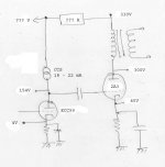
OK, I gave up trying to draw this in Illustrator, and hand-drew it and scanned it in. It's pretty bad, but I tried to clean up the text so it's semi-legible.
Questions:
* The obvious one is the question marks - what should the B+ for the driver stage be? How much does the tube need to be able to swing? This will tell me what the CCS needs to dissipate, which will tell me how to set it up and heatsink it and so on. 300V would be a safe answer here, but I'd like to drop as much as possible in the resistor (???R), so that the power dissipated in the CCS isn't any more than absolutely necessary.
* Slew rate - I found the right thread this time, and it answered a lot of my questions. It still leaves me with my basic question though - I can calculate how much current I need, how do I calculate how much current the driver can supply? I think this will be a very obvious answer.
Attachments
Current and capacitors
You find the gain of the 2A3, (probably about 4). Then use the Miller equation to find the Miller capacitance. Cm = Cag x (1 + A), so that gives about 82.5pF. Then add Cgf (7.5pF) to give 90pF, add a bit for strays, and 100pF is probably about right.
If the 2A3 is biased to 45V, then the largest sinewave that can be applied is 45Vpk.
At 20kHz, 100pF has a reactance of 80k.
If you apply 45Vpk across 80k, you require 565uApk. This current is at 90 degrees to the applied voltage, so it represents a vertical movement from the driver's operating point of +565uA and -565uA. Current from your anode load resistor will simply be diverted from the valve to the capacitance. Because valves aren't very linear when changing current at constant voltage, you need quite a large quiescent current to make the capacitive current proportionately small. 10:1 is a nice ratio, but it's best to inspect the curves and check that you are well clear of the knee at the bottom. 18 -22mA should be plenty.
Thanks EC8010. I found your post(s) about how to draw the elliptical load line for such a situation.
That's the piece of information I was looking for. Like I said, I figured it would be obvious.
I was thinking of something this morning. Can we hook up a CCS this way?
This puts the CCS in the position of the PS dropper resistor. Because of the filter cap C1, I think the tube will only see the plate load R, and not the few Mohm/Gohm of the CCS. But, would this still serve the function of providing a constant bias current for the tube? The advantage I see with this is a much lower power dissipation in the CCS transistors, which would probably make it easier to build and longer lasting. But, I don't think anyone does it this way, so there must be a reason why.
Edit: OK, I think I know why that won't work. Variations in current will be supplied by the stored energy in the capacitor, and so the current won't be constant. Never mind.
Current from your anode load resistor will simply be diverted from the valve to the capacitance.
That's the piece of information I was looking for. Like I said, I figured it would be obvious.
I was thinking of something this morning. Can we hook up a CCS this way?
Code:
                                 CCS
    -----------------------------0O0--------------------------o B+ (330V)
    |         |                 <----            |         |
    |         /               18 - 22 mA         3         |
C1  =         \                                  3 OPT     =
    |         / Plate R                          3         |
    V         |                                  |         V
              |                                  |
              |---------------||----------------2A3
             ECC99                               |
              |                                  |
              |                                  |
This puts the CCS in the position of the PS dropper resistor. Because of the filter cap C1, I think the tube will only see the plate load R, and not the few Mohm/Gohm of the CCS. But, would this still serve the function of providing a constant bias current for the tube? The advantage I see with this is a much lower power dissipation in the CCS transistors, which would probably make it easier to build and longer lasting. But, I don't think anyone does it this way, so there must be a reason why.
Edit: OK, I think I know why that won't work. Variations in current will be supplied by the stored energy in the capacitor, and so the current won't be constant. Never mind.
Exactly. Placing a CCS in the HT line gives excellent filtering, but not much else. If your CCS was in the anode circuit and dropped 120V while passing 20mA, it would dissipate 2.4W. An MJE350 can dissipate that quite cheerfully provided that it's on a heatsink, so where's the problem?
Just being paranoid 🙂 And that goes back to an earlier question - how much drop do I need in the CCS? Or, how much 'headroom' do I need between the plate voltage and B+? It needs to swing 45V, so would double that (90V) be enough (plus a marging for the CCS drop needed to keep it functioning correctly)? Hmm.. that comes to around 120V... so maybe that's how you came up with that figure.
I like to be able to swing double the expected swing. You need to swing 45V positive, so 90V of capability would be nice. I suggested 120V because that's probably the amount you need to drop from the HT to your anode voltage, and yes, you need a bit of a margin for the CCS.
Thanks. I think I can do this now 🙂
I'll probably add a small dropper resistor between the driver and 2A3 B+ points anyway, don't want all my tubes getting their B+ from the same point in the PS. If I remember, that might help prevent motorboating or something like that.
I suggested 120V because that's probably the amount you need to drop from the HT to your anode voltage
I'll probably add a small dropper resistor between the driver and 2A3 B+ points anyway, don't want all my tubes getting their B+ from the same point in the PS. If I remember, that might help prevent motorboating or something like that.
If they all obtain their power from the same point, you risk RF oscillation. When you resistor/capacitor decouple, you risk motorboating. You just can't win! (But the risk of motorboating is very small.)
I think I'll stick with a pre-designed CCS kit for this time. Unless I find hold-my-hand level instructions for using this transistor, I'd rather not try experiments on my own, because I know even less about transistors than I do about tubes 🙂
I'll keep that in mind for the future though. I know you're an advocate of regulated power supplies for all stages. I also know that you use tube regulators, but something like this would probably be quite a bit better than no regulator at all, right? If I decide to take my amp even further, I could try this on the 2A3 supply, if that makes sense.
P.S. I had a lucky find at the surplus store today - 680 ohm 50W aluminum clad finned resistors that look like they'll fit in the same holes I drilled for my 2A3s cathode bias resistors. The ones in my amp are 880 ohms (that's the part in the original schematic, probably because that's the only 50W resistor they carry. It's probably better suited for a 300B than a 2A3), which gives me about 53mA, so 680 is probably perfect - it'll push it a little over 60mA, but not too much. And I think I won't have to drill new holes either 🙂
Hi,
Well, just like yourself I'm no sandman either (sic)...the IXYS however are so easy to use it's almost as if they had us in mind when they developped these.
Anyways, work with what you're comfortable with.
Later on you can take a look at Pete Millet's excellent site holding some info on CCSs amongst other intersting stuff.
PETE'S EXPERIMENTS
Cheers,😉
I think I'll stick with a pre-designed CCS kit for this time. Unless I find hold-my-hand level instructions for using this transistor, I'd rather not try experiments on my own, because I know even less about transistors than I do about tubes
Well, just like yourself I'm no sandman either (sic)...the IXYS however are so easy to use it's almost as if they had us in mind when they developped these.
Anyways, work with what you're comfortable with.
Later on you can take a look at Pete Millet's excellent site holding some info on CCSs amongst other intersting stuff.
PETE'S EXPERIMENTS
Cheers,😉
So this is a single chip current regulator, not a replacement transistor in one of these CCS PCBs. OK, then I might be able to handle this 🙂
Thanks... I'd seen that page before, but skimmed it because it looked too involved. Surprisingly enough, this time round I understood most of it 🙂
Thanks... I'd seen that page before, but skimmed it because it looked too involved. Surprisingly enough, this time round I understood most of it 🙂
Hi Saurav,
I've just seen this thread and have nothing really to add to EC's thorough posts.
Even though the ECC99 could be run in this application at much lower anode currents, I simply find it sounds clearer with > 20mA of current through it, and have found that to be so over a range of anode voltages. If you can dissipate the power in the CCS, go for it. If I have time this weekend, I'm going to breadboard a ECC99 (CCS) -> 6V6 / 807 trioded in PP just for the hell of it. Because I need a max swing of around 30Vpk, I'm going to have 100V across the CCS and the '99 at 150V/22/-4. If in my system it's still too much gain (likely for the 6V6) I'm going to get out the 6H30's again.
Good on you for giving this a try, and I'm looking forward to hearing your opinions of the result.
I have no practical experience with the C4S to add though.
I've just seen this thread
That's good, I was all heartbroken that you seemed to be ignoring me 😉
If you can dissipate the power in the CCS, go for it.
Well, if I find things getting too hot, I could reduce the voltage overhead in the CCS a bit, that would be one way of reducing power dissipation while keeping it at the same current. Also, if I reduce by 2A3's cathode resistor and keep the B+ the same, I think I'll move the operating point to a lower bias voltage. So, reducing the CCS voltage overhead by a few volts might not hurt that much. I need t look at the 2A3 curves in more detail though, I'm not sure if increasing plate current without increasing plate voltage is a good idea.
Thanks,
Saurav
Saurav said:Well, if I find things getting too hot, I could reduce the voltage overhead in the CCS a bit, that would be one way of reducing power dissipation while keeping it at the same current.
Or you could use a bigger heatsink. These can often be found cheap on old SS amps that have expired etc for $0.
Also, if I reduce by 2A3's cathode resistor and keep the B+ the same, I think I'll move the operating point to a lower bias voltage.
I'd keep the 2A3 at the same op point if possible, if for no other reason than it's one less thing youve changed in the experiement, so you can narrow down the sonic changes to the front end.
So, reducing the CCS voltage overhead by a few volts might not hurt that much.
Probably not but the rule-of-thumb I use for powertube drivers is 3dB of headroom, and factoring in losses across the CCS you're near that now.
I need t look at the 2A3 curves in more detail though, I'm not sure if increasing plate current without increasing plate voltage is a good idea.
Should be fine. It'll give a bit more power, but if you're at the "classic" 2A3 op point of 250Va-k, 60mA, -45V you're right at the plate dissipation limits. Sovteks will apparently take more power, but I'm not sure how they'll sound or their longevity. Keep the 2A3 the same for the moment.
- Status
- Not open for further replies.
- Home
- Amplifiers
- Tubes / Valves
- CCS loaded ECC99 calculations/questions